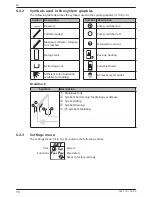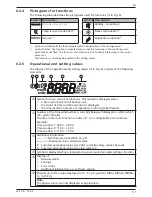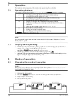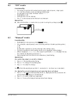
8
742.110 | 14.50
EN
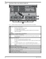
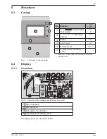
4.3.1
Position of the connection terminals
L R1
N
PE
PE
PE
PE
N
R1
R
S
5
4
3
2
1
R
S
0–10
11
2
15
13
14
6
7
11
13
15
18
Fig. 3: Terminal clamps in the lower part of the controller (terminal cover removed)
Power connection
terminal block:
L
1x phase conductor (mains input)
R1
1x output (TRIAC, for pump)
N
2x neutral conductor (common neutral conductors for mains power
input and output)
Note
Output
R1
is protected by an electronic fuse.
Protective conductor
terminal block:
PE
4x protective earth (common protective earth for
power connection
terminal block)
Signals
terminal block:
1
–
4
4x sensor input (Pt1000 temperature sensor)
5
1x sensor input (Pt1000 temperature sensor or pulse water meter input)
R
S
not used
0–10
R1
1x control output (for
0–10 V
controlled high-efficiency pumps)
6x mass connection (common mass for sensor inputs and control out-
puts)
Pin strip, for internal use only
Cable openings on the rear side of the casing
Upper
strain relief clamps (2 identical plastic links, each with 2 strain relief clamps,
supplied in the scope of delivery)
Lower
strain relief clamps
Cable openings at the bottom of the casing
Содержание TR-A501T-U
Страница 47: ...47 742 110 14 50 EN 18 Notes ...
Страница 48: ...48 742 110 14 50 EN 742110 ...


