SOFTWARE
79
8.1.5. GRAPHIC INTERFACE
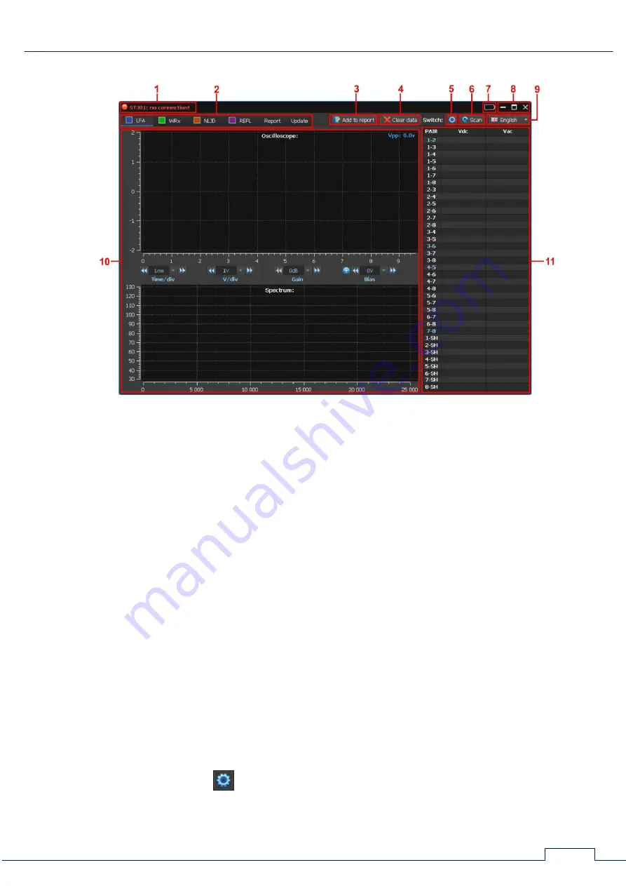
Fig.61
In Fig.61:
1 - PC connection indicator
2 - buttons to turn on the devices or report mode or firmware updating mode
3 - button to add current information to the report
4 - button to delete current test results (creation a new report)
5 - button to turn on/off the Switch configuration mode
6 - button to turn on the AUTOMATED mode of the Switch
7 - accumulator charge level indicator
8 - control of window
9 - switching interface language
10 - controls and analysis results in the selected device and mode of operation
11 - information window, where, depending on the device turned on, it is displayed:
measured value of DC/AC voltage (LFA)
number of detected signals (WR)
response level (NLJD)
distance to the heterogeneity with the maximum response level and the response level (REF)
8.1.6. ELECTRONIC SWITCH
The Switch used by all devices, except the power mains testing mode (WR). The software
allows you to configure the Switch and manage it with automated or manual cable testing.
To the Switch setup, click
(Fig.61, item 5). The setup window will appear on the screen.


