background image

Trace Oxygen Analyzer

Teledyne Analytical Instruments

i

OPERATING INSTRUCTIONS FOR

MODEL  3000ZA

Trace Oxygen Analyzer

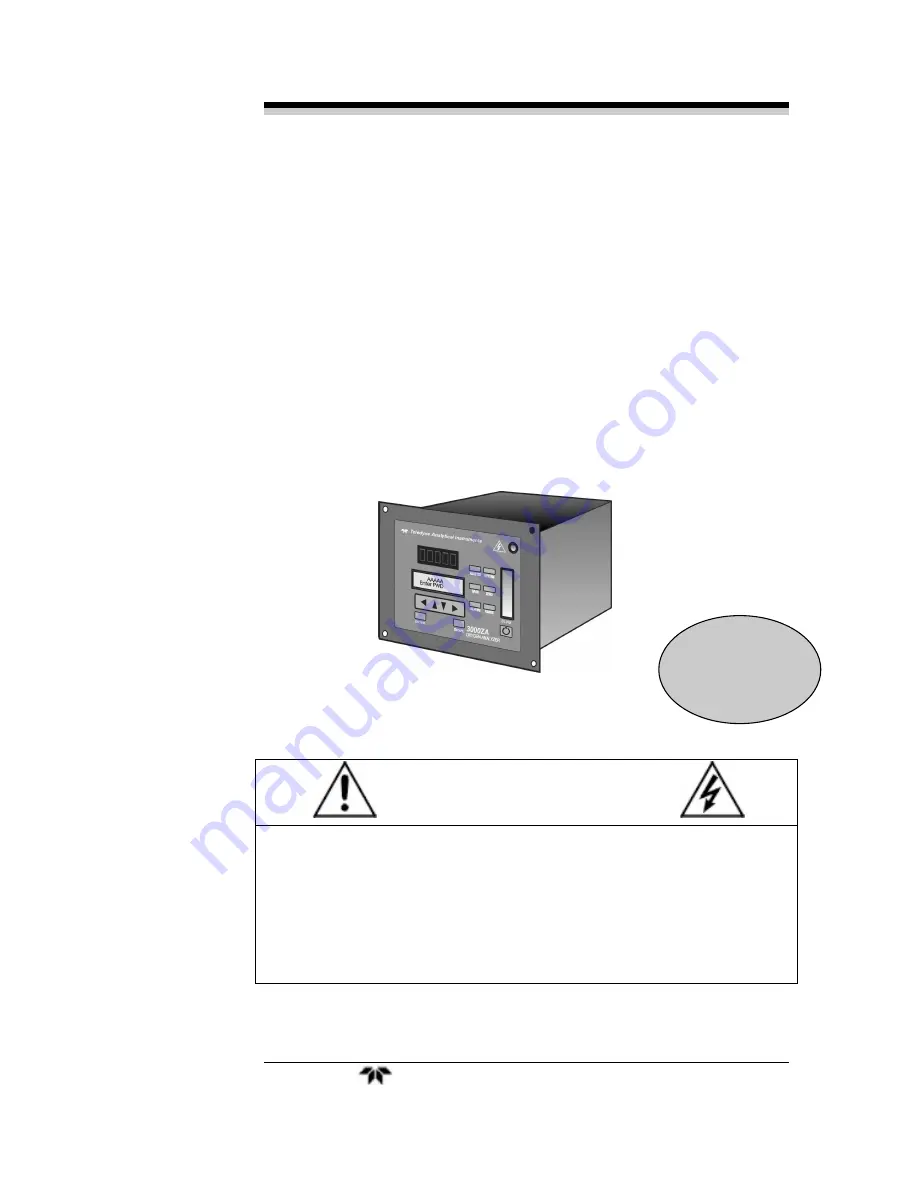
DANGER

Toxic gases and or flammable liquids may be present in this monitoring system.

Personal protective equipment may be required when servicing this instrument.

Hazardous voltages exist on certain components internally which may persist
for a time even after the power is turned off and disconnected.

Only authorized personnel should conduct maintenance and/or servicing.
Before conducting any maintenance or servicing, consult with authorized
supervisor/manager.

P/N M75739

4/10/04

Содержание 3000ZA

Страница 1: ...tem Personal protective equipment may be required when servicing this instrument Hazardous voltages exist on certain components internally which may persist for a time even after the power is turned o...

Страница 2: ...of any parts in so far as such alterations do not adversely affect our warranty Important Notice This instrument provides measurement readings to its user and serves as a tool by which valuable data c...

Страница 3: ...Instrument Serial Number _______________________ Options Included in the Instrument with the Above Serial Number 3000ZA C In addition to all the standard features this model also has separate ports f...

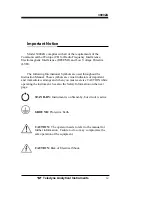
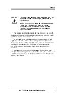
Страница 4: ...used throughout the Instruction Manual These symbols are visual indicators of important and immediate warnings and when you must exercise CAUTION while operating the instrument See also the Safety In...

Страница 5: ...rocedures which if not followed could cause bodily Injury and or damage the instrument CAUTION HOT SURFACE WARNING This warning is specific to heated components within the instrument Failure to heed t...

Страница 6: ...new analyzer Please read this manual and keep it available Occasionally some instruments are customized for a particular application or features and or options added per customer requests Please chec...

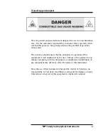
Страница 7: ...ist The customer should ensure that the principles of operation of this equipment is well understood by the user Misuse of this product in any manner tampering with its components or unauthorized subs...

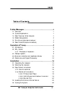
Страница 8: ...8 2 2 ZrO2 Sensor 8 2 2 1 Principles of Operation 8 2 3 Sample System 9 2 4 Zirconium Oxide Sensor Application Notes 10 2 5 Electronics and Signal Processing 10 Installation 14 3 1 Unpacking the Analy...

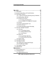
Страница 9: ...lf Diagnostic Test 37 4 3 6 Version Screen 38 4 3 7 Showing Negative Oxygen Readings 38 4 4 The Zero and Span Functions 39 4 4 1 Zero Cal 40 4 4 1 1 Auto Mode Zeroing 40 4 4 1 2 Manual Mode Zeroing 41...

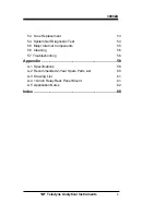
Страница 10: ...ystem Self Diagnostic Test 54 5 5 Major Internal Components 55 5 6 Cleaning 56 5 7 Troubleshooting 56 Appendix 58 A 1 Specifications 58 A 2 Recommended 2 Year Spare Parts List 60 A 3 Drawing List 61 A...

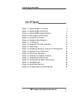
Страница 11: ...ck Diagram 13 Figure 3 1 Front Panel 15 Figure 3 2 Required Front Door Clearance 15 Figure 3 3 Rear Panel 16 Figure 3 4 Equipment Interface Connector Pin Arrangement 19 Figure 3 5 Remote Probe Connect...

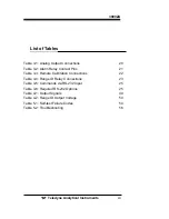
Страница 12: ...Relay Contact Pins 21 Table 3 3 Remote Calibration Connections 22 Table 3 4 Range ID Relay Connections 23 Table 3 5 Commands via RS 232 Input 25 Table 3 6 Required RS 232 Options 25 Table 4 1 Output S...

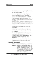
Страница 13: ...ions of the Model 3000ZA are Monitoring inert gas blanketing Air separation and liquefaction Chemical reaction monitoring Semiconductor manufacturing Petrochemical process control Quality assurance Ga...

Страница 14: ...able concentration alarms and a system failure alarm Extensive self diagnostic testing at startup and on demand with continuous power supply monitoring CE compliance RS 232 serial digital port for use...

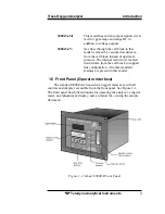
Страница 15: ...ressure The internal restrictor is located downstream from the cell block to support this configuration All other standard features are present in this model 1 5 Front Panel Operator Interface The sta...

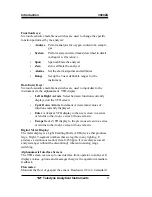
Страница 16: ...the VFD screen Up Down Arrows Increment or decrement values of functions currently displayed Enter Advances VFD display to the next screen in a series or returns to the Analyze screen if none remain...

Страница 17: ...or access to the ZrO2 sensor the front panel swings open when the latch in the upper right corner of the panel is pressed all the way in with a narrow gauge tool Accessing the main circuit board requi...

Страница 18: ...allow external control of analyzer calibration Calibration Contact To notify external equipment that instrument is being calibrated and readings are not monitoring sample Range ID Contacts Four separa...

Страница 19: ...Trace Oxygen Analyzer Introduction Teledyne Analytical Instruments 7 scheduled calibrations can vary 2 3 per day...

Страница 20: ...the analyzer 2 2 ZrO2 Sensor 2 2 1 Principles of Operation Teledyne s zirconium oxide sensor is a miniature solid state sensor It uses a stabilized zirconia disc as an electrolyte with a sensing elect...

Страница 21: ...he sample system for the standard instrument incorporates compression tube fittings for sample inlet and 1 4 outlet tube connections at the rear panel The sample or calibration gas that flows through...

Страница 22: ...g SOx H2S silicone vapor and adhesives must not enter the sensor These components adversely affect the performance of the sensor Dust and oil should be filtered from the sample gas Water vapor in cont...

Страница 23: ...rolled by the microprocessor The high operating temperature of the ZrO2 sensor is required for proper operation of the sensor The amplifier PCB contains a circuit that drives the heater embedded in th...

Страница 24: ...Operational Theory 3000ZA Teledyne Analytical Instruments 12 Figure 2 3 Component Location...

Страница 25: ...Trace Oxygen Analyzer Operational Theory Teledyne Analytical Instruments 13 Figure 2 4 Electronic Block Diagram...

Страница 26: ...2 Mounting the Analyzer The Model 3000ZA is for indoor use in a general purpose area It is NOT for hazardous environments of any type The standard model is designed for flush panel mounting Figure 3...

Страница 27: ...d on the left edge and doubles as the door that provides access to the sensor and cell block inside the instrument The door latch is spring loaded and will swing open when the button in the center of...

Страница 28: ...th Span and Zero Ports 3 3 1 Gas Connections Before using this instrument it should be determined if the unit will be used for pressurized service or vacuum service and low pressure applications The k...

Страница 29: ...CAN CAUSE DAMAGE TO THE SENSOR The unit is manufactured with 1 4 tube fittings and includes 6 mm adapters for metric system installations For a safe connection 1 Insert the tube into the fitting and...

Страница 30: ...safety considerations are the same as prescribed for the SAMPLE IN inlet above 3 3 2 Electrical Connections For safe connections no uninsulated wiring should be able to come in contact with fingers to...

Страница 31: ...the rear panel of the analyzer The pin numbers for each input output function are given where each function is described in the paragraphs below Figure 3 4 Equipment Interface Connector Pin Arrangemen...

Страница 32: ...open and normally closed contact connections The contact connections are shown in Table 3 2 They are capable of switching up to 3 amperes at 250 V ac into a resistive load The connectors are Threshold...

Страница 33: ...42 Threshold Alarm 2 normally closed contact 44 Threshold Alarm 2 moving contact 43 Threshold Alarm 2 normally open contact 36 System Alarm normally closed contact 20 System Alarm moving contact 37 Sy...

Страница 34: ...Remote Span 40 Cal Contact 41 Cal Contact Remote Calibration Protocol To properly time the Digital Remote Cal Inputs to the Model 3000ZA Analyzer the customer s controller must monitor the Cal Relay C...

Страница 35: ...ned to relays in ascending order Low range is assigned to Range 1 ID Medium range is assigned to Range 2 ID and High range is assigned to Range 3 ID The fourth range is reserved for the Air Cal Range...

Страница 36: ...100 mA If two lines are ON at the same time each must be limited to 50 mA etc If more current and or a different voltage is required use a relay power amplifier or other matching circuitry to provide...

Страница 37: ...ich alarms if any are disabled AL x DISABLED Which alarms if any are tripped AL x ON Each status output is followed by a carriage return and line feed Three input functions using RS 232 have been impl...

Страница 38: ...put is a standard RS 232 serial communications port used to connect the analyzer to a computer terminal or other digital device It requires a standard 9 pin D connector The data is status information...

Страница 39: ...Make sure there are no leaks Check the integrity and accuracy of the electrical connections Make sure there are no exposed conductors Check that inlet sample pressure is within the accepted range see...

Страница 40: ...hoose autoranging or select a fixed range of analysis as required Set alarm setpoints and modes of alarm operation latching failsafe etc Before you configure your 3000ZA these default values are in ef...

Страница 41: ...r via the function buttons The six function buttons on the analyzer are Analyze This is the normal operating mode The analyzer monitors the oxygen content of the sample displays the percent of oxygen...

Страница 42: ...ess password restrictions apply The order as presented in this manual is appropriate for an initial setup Each of these functions is described in greater detail in the following procedures The VFD scr...

Страница 43: ...perator must log out to activate it Until then anyone can continue to operate the instrument without entering the new password Only one password can be defined Before a unique password is assigned the...

Страница 44: ...wn keys When TRACK is selected the analog outputs 0 1 VDC and 4 20 ma and the range ID contacts will track the instrument readings during calibration either zero or span TRACK is the factory default W...

Страница 45: ...nal Auto Cal control where possible The internal clock in the Model 3000ZA is acurate to 2 3 Accordingly internally scheduled calibrations can vary 2 3 per day To setup an Auto Cal cycle Choose System...

Страница 46: ...word will be displayed automatically by the microprocessor The operator just presses the Enter key to be allowed total access to the instrument s features Note If you use password security it is advis...

Страница 47: ...ce to proceed PSWD Restrictions Removed In a few seconds you will be given the opportunity to change this password or keep it and go on Change Password ENT Yes ESC No Press Escape to move on or procee...

Страница 48: ...s t u v w x y z 0 1 2 3 4 5 6 7 8 9 When you have finished typing the new password press Enter A verification screen appears The screen will prompt you to retype your password for verification A A A A...

Страница 49: ...tem function TRAK HLD Auto Cal PSWD Logout More Use the __ arrow keys to position the blinking over the Logout function and press Enter to Log out The screen will display the message Protected Until P...

Страница 50: ...Chapter 5 Maintenance and Troubleshooting for number code information The results screen alternates for a time with Press Any Key To Continue Then the analyzer returns to the initial System screen 4 3...

Страница 51: ...electronics and the internal and external sampling systems It will improve performance beyond published specification limits The analyzer is calibrated using zero and span gases Any suitable oxygen fr...

Страница 52: ...ted to the instrument If you get a CELL FAILURE message skip to Section 4 4 1 3 4 4 1 1 AUTO MODE ZEROING Press Zero to enter the zero function mode The screen allows you to select whether the zero ca...

Страница 53: ...etermined rate It calculates the differences between successive samplings and displays the rate of change as Slope a value in parts per million per second ppm s ppm Zero Slope ppm s Note It takes seve...

Страница 54: ...can also be performed in manual mode where the operator determines when the span concentration reading is acceptable and manually exits the function 4 4 2 1 AUTO MODE SPANNING Press Span to enter the...

Страница 55: ...automatically returns to the analyze mode 4 4 2 2 MANUAL MODE SPANNING Press Span to start the Span function The screen that appears allows you to select whether the span calibration is to be performe...

Страница 56: ...s the Analyze function 4 4 3 Span Failure The analyzer checks the output of the cell at the end of the span If the raw output of the cell is too low the span will not be accepted The analyzer will ret...

Страница 57: ...Decide how your alarms should be configured The choice will depend upon your process Consider the following four points 1 Which if any of the alarms are to be high alarms and which if any are to be l...

Страница 58: ...n 4 3 3 to enter your password Once you have clearance to proceed enter the Alarm function Press the Alarm button on the front panel to enter the Alarm function Make sure that AL 1 is blinking AL 1 AL...

Страница 59: ...ng In this mode the microprocessor automatically responds to concentration changes by switching ranges for optimum readout sensitivity If the current range limits are exceeded the instrument will auto...

Страница 60: ...4 6 2 Fixed Range Analysis The autoranging mode of the instrument can be overridden forcing the analyzer DC outputs to stay in a single predetermined range To switch from autoranging to fixed range an...

Страница 61: ...y you can press the Analyze button at any time to return to analyzing your sample 4 8 Signal Output The standard Model 3000ZA Trace Oxygen Analyzer is equipped with two 0 1 VDC analog output terminals...

Страница 62: ...The following table gives the range ID output for each analysis range Table 4 2 Range ID Output Voltage Range Voltage V Current mA LO 0 25 8 MED 0 50 12 HI 0 75 16 IMPORTANT In the event of loss of fl...

Страница 63: ...Trace Oxygen Analyzer Operation Teledyne Analytical Instruments 51...

Страница 64: ...he cell reaches the end of its useful life it is replaced The spent sensor should be discarded according to local regulations 5 2 1 Removing the Sensor The ZrO2 sensor is located inside the nylon cell...

Страница 65: ...r and install a new sensor by matching the orientation notch on the sensor to the silkscreen on the sensor holder Figure 5 1 Replacing the ZrO2 Sensor 5 3 Fuse Replacement 1 Place small screwdriver in...

Страница 66: ...e 5 2 American Fuses European Fuses Figure 5 3 Installing Fuses 5 4 System Self Diagnostic Test 1 Press the System button to enter the system mode 2 Use the __ arrow keys to move to More and press Ent...

Страница 67: ...l as described earlier Other internal components are accessed by removing the rear panel and sliding out the entire chassis See Figure 5 4 below The gas piping is illustrated in Figures 2 1 and Figure...

Страница 68: ...outside surfaces with a soft cloth dampened slightly with plain clean water Do not use any harsh solvents such as paint thinner or benzene For panel mounted instruments clean the front panel as presc...

Страница 69: ...th of vent tubing to dilute or minimize oxygen diffusion from vent to sensor Inaccurate zero operation i e user has zeroed the instrument using a gas concen tration much higher than normal for a zero...

Страница 70: ...ss steel 90 Response Time 65 seconds at 25 C 77 F on 10 ppm range 100 seconds on 1 ppm range Ranges Option a 0 10 to 0 200 ppm O2 0 1 ppm analysis possible Option b 0 10 to 0 1000 ppm O2 Autoranging w...

Страница 71: ...ramge 5 of full scale over operating temperature range except 0 1 ppm analysis range once thermal equilibrium is reached 0 2 ppm on 0 1 ppm analysis range once thermal equilibrium is reached Analog o...

Страница 72: ...V 5x20mm Slow Blow 1 A68314 Back Panel Connector Kit 1 A68729 Restrictor kit A minimum charge is applicable to spare parts orders Note Orders for replacement parts should include the part number if av...

Страница 73: ...en Analyzer Appendix Teledyne Analytical Instruments A 3 Drawing List D 75739 Final Assembly D 75738 Outline Drawing A 4 19 inch Relay Rack Panel Mount Figure A 1 Single and Dual 19 Rack Mounts dimens...

Страница 74: ...w rate will result in slow response to O2 changes in the sample stream The span flow rate should be the approximately same as the sample flow rate RESTRICTION DEVICES For proper operation all 3000 ser...

Страница 75: ...commended 3000TA EXAMPLES Example 1 With a incoming pressure of 10 psig the std restrictor blue dot will provide a flow rate of 0 76 SLPM Upstream of the restrictor the sample line pressure will be 10...

Страница 76: ...flow rate as the sample gas When restrictors are used the gas pressure must be adjusted to achieve the proper flow rate OPERATION WITHOUT A RESTRICTOR DEVICE Operation without a restrictor device is...

Страница 77: ...Trace Oxygen Analyzer Appendix Teledyne Analytical Instruments 1 SCFH 0 476 SLPM...

Страница 78: ...lock diagram 10 by pass 63 bypass line 17 by pass valve 62 calibration automatic zero 39 connections 21 manual zero 40 remote cal protocol 21 remote control 20 span 21 zero 20 calibration contact 6 21...

Страница 79: ...nal vi measurement error 9 membrane switches See keys meter 3 4 microcontroller 9 microprocessor 7 10 55 model designation 2 model information iii MORE 30 motherboard 10 mounting holes 13 network I O...

Страница 80: ...re 10 sensor removal 51 serial number iii serial port 2 setpoint See alarm setpoint setpoint units 45 setting ranges 46 show negative 28 SHOW NEGATIVE 30 signal processing 9 slope 39 40 42 43 software...

Страница 81: ...Trace Oxygen Analyzer Index Teledyne Analytical Instruments...

Отзывы: