SOFTWARE
99
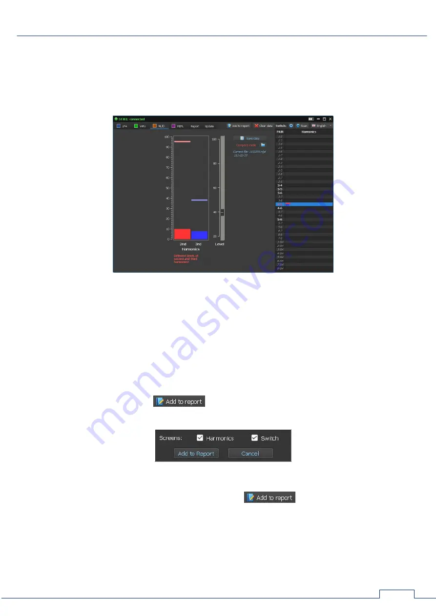
The mismatch message is displayed below the indicator. (Fig.76, item 7).
Fig. 76 shows the situation when the current levels of the second and third harmonics on the
"4-5" pair significantly exceed the previously measured ones.
This may be due to the appearance of nonlinearity when connecting an electronic device to the
cable.
It is possible that the current response levels are less than previously measured (Fig.77).
Fig.77
Attention!
If the level of the probe signal does not correspond to the level in the saved file,
when the comparison mode is activated, the message appears on the screen:
Different levels of the probing signal (in the file - <XX%>)
In this case, set the level of the probing signal corresponding to the saved level and re-scan.
8.4.4. REPORT MODE
To create report files click
. The menu will be displayed on the screen (Fig. 78)
with a list of information that can be saved.
Fig.78
After selecting screenshots and tables and clicking
, the program generates files
with specific names and extensions.
When using NLJD, it is possible to save graphic information (Fig.79) as PNG files:
screenshot of the level 2 and 3 harmonics indicator ("Harmonics" check box);
Switch table screenshot ("Switch" check box).


