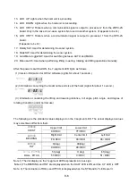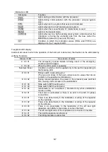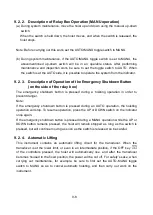
9-9
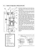
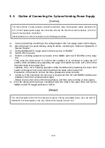
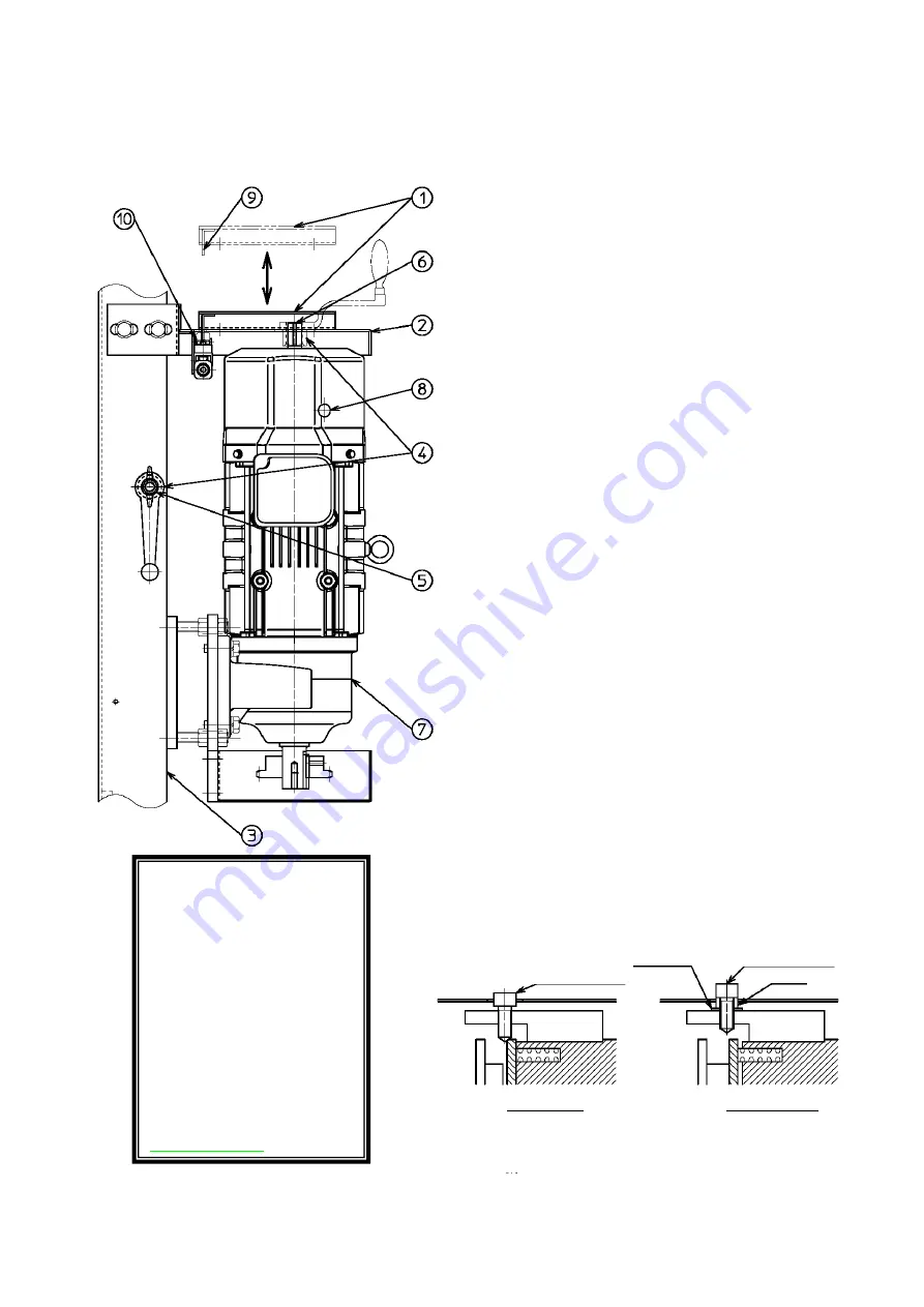
9. 3. Outline of Operation of Manual Handle
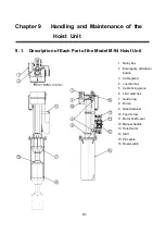
1. Motor shaft cover
2. Motor cover
3. Column
4. Manual handle
5. Wing nut
6. Motor shaft
7. Hoist motor
8. Brake slackening bolt
9. Tab on motor shaft
cover
10. Microswitch
1. Remove the 4 fixing screws of the motor shaft cover,
then remove the motor shaft cover from the motor
cover. (Take care not to lose the motor shaft cover
and the screws.)
2. Remove the wing nut and remove the manual handle
fixed to the column, then set the manual handle on
the motor, as shown in the figure. (Screw the
removed wing nut onto the bolt.)
3. Remove the two diagonally opposite brake slackening
bolts, remove the spacer and seal washer, and then
once again screw in the bolts using a hex key so that
the brake is released. (Note 1) When doing this, take
care not to tighten the brake slackening bolts to an
excessively degree. (While checking to see if the
brake is released, turn the brake slackening bolts.)
4. Turning the manual handle to the right or left causes
the hoist to ascend or descend. Turn the handle in the
desired direction to the target position.
5. Upon completion of the above work, once again
return the various parts to their original positions. For
safety’s sake, re-install the spacer and seal washer
removed in step 3, in their original positions. (Turn the
handle slightly and confirm that the brake is
functioning.)
6. Remove the manual handle from the motor shaft, and
fix it to the bolt on the column using the wing nut.
7. Finally, fix the motor shaft cover to the motor cover.
When doing this, pass the tab at the front edge of the
motor shaft cover through the hole in the motor cover,
and fix it so that the microswitch at the rear operates
without fail.
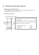
(Note 2)
Note 1. There are two bolts in symmetrical locations. Turn both
of them
You can turn the bolts using the hex key in the toolbox
for maintenance parts.
Brake slackening bolt
Seal washer
Spacer
Brake slackening bolt
When relased
During operation
Note 2. If this microswitch fails to operate, the hoist motor will
not operate.
Содержание KCS-5200
Страница 1: ...Model KCS 5200 Color Scanning Sonar Operation Manual Ver 1 48 E Rev 0...
Страница 2: ......
Страница 14: ......
Страница 22: ...2 4...
Страница 28: ...3 6...
Страница 46: ...5 12 A display example of Net Cast Net Set and VRM Wake Net Cast mark Net Set ring mark VRM VRM distance...
Страница 50: ...5 16...
Страница 78: ...6 28 Menu Screen Sub Screen Orthogonal Display Axis...
Страница 80: ...6 30...
Страница 84: ...7 4...
Страница 90: ...8 6...
Страница 106: ...9 16...
Страница 116: ...10 10...

