9-14
9. 7. Precautions Concerning the Protrusion of the Hoist Unit
into Equipment at the Bottom of the Boat
9. 7. 1. Adjusting the Clearance Between the Pressure Receiving Ring
and the Skirt
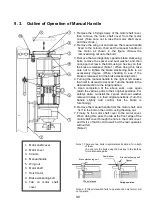
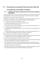
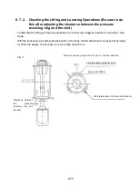
The optimum clearance (Fig. 1) at the above locations is between 2 and 3 mm. Note that if the clearance
at these locations is 5 mm or more, there may also be cases in which trouble occurs due to vibration
when the boat is moving, and also due to hoisting trouble.
This clearance will change due to strain in the skirt during local manufacture, and also when the skirt is
being welded. For this reason, be very careful of the following points during manufacture.
1-1)
Points to observe during local manufacture of the skirt
・
Use welded steel plate for marine use as the raw material of the skirt.
・
Be sure to anneal the skirt during manufacture.
・
The eccentricity of the skirt must be no more than 2 mm, and the ID tolerance must be within 1.5 mm.
1-2)
Welding the skirt to the bottom of the boat
・
The diameter of the hole for installing the skirt on the bottom of the boat must be the skirt OD plus no
more than 5 mm.
・
The strain generated when the skirt is welded to the bottom of the boat must be within about
2 mm.
1-3)
Adjusting the clearance between the pressure receiving ring and the skirt
After welding the skirt, carry out adjustment using the following procedure.
1. Clean the flange of the skirt, then pass the packing through the bolt hole and install it. Next, place the
mounting hoist unit on the skirt, and temporarily fix it with three or four bolts.
2. Using manual or automatic operation, lower the host to the lower limit.
3. Measure the clearance between the outside part of the bottom of the boat and each of three receiving
rings (parts made of plastic), and verify that it is between 2 and 5 mm.
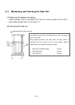
4. If the clearance is defective, raise the hoist unit to the upper limit, remove the temporarily inserted
bolts, raise the hoist unit, and then perform adjustment of the clearance by insert or removing spacers
(4037943) at the pressure receiving ring part.
5. Once again, lower the hoist unit, and measure the clearance. If the clearance is satisfactory, coat the
flange packing with packing material, and tighten the flange to the correct torque.
Содержание KCS-5200
Страница 1: ...Model KCS 5200 Color Scanning Sonar Operation Manual Ver 1 48 E Rev 0...
Страница 2: ......
Страница 14: ......
Страница 22: ...2 4...
Страница 28: ...3 6...
Страница 46: ...5 12 A display example of Net Cast Net Set and VRM Wake Net Cast mark Net Set ring mark VRM VRM distance...
Страница 50: ...5 16...
Страница 78: ...6 28 Menu Screen Sub Screen Orthogonal Display Axis...
Страница 80: ...6 30...
Страница 84: ...7 4...
Страница 90: ...8 6...
Страница 106: ...9 16...
Страница 116: ...10 10...


