


30
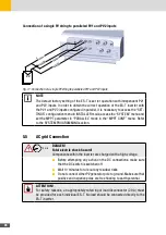
ATTENTION!
The NEUTRAL conductor (N) of the EPS port is floating. If local regulations require
that the NEUTRAL conductor (N) must be connected to the earth potential, it is
necessary to provide an external electrical connection between the PE protective
conductor and the NEUTRAL conductor connected to the EPS port. Not providing
the connection between NEUTRAL and PE can lead to the malfunction of the RCD
protection systems provided for the privileged line and placed downstream of the
inverter and/or to the malfunction of the connected loads.
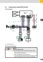
NOTE
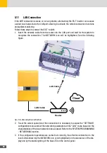
For safety reason, the operation of the EPS port is disabled as per ES-T default
factory setting. To enable the operation of the EPS port, it is necessary to access
the “SETTINGS” configuration menu in INSTALLER mode, access the “SYSTEM”
menu and select “ON” in the “EPS” menu. Refer to the SYSTEM PROGRAMMING
section
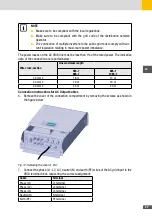
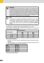
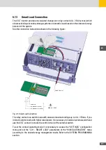
For safety reasons, an appropriately rated input load disconnector (20 A) must be provided for
each individual ES-T. No load should be connected directly to the ES-T inverter.
The power losses on the EPS line must be less than 1% of the rated power. The indicative data
of the connection are reported below:
Wire cross-section
Line maximum length
5ES-T
6ES-T
8ES-T
10ES-T
2.5 mm
2
18 m
12 m
4.0 mm
2
29 m
19 m
6.0 mm
2
45 m
30 m
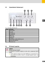
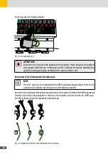
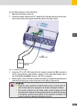
EPS Connection instructions
1. Remove the cover of the connection compartment by removing the screws as shown in
the
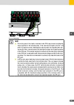
2. Connect the phase (L1, L2, L3), neutral (N) and earth (PE) wires of the EPS output to the
EPS terminal block respecting the correct assignment:
Cable
Terminal
Phase (L1)
L1 terminal
Phase (L2)
L2 terminal
Phase (L3)
L3 terminal
Neutral (N)
N terminal
Earth (PE)
PE terminal
For wiring see the following figure:
Содержание 10ES-T
Страница 1: ...Instruction Manual SolarMax ES T series 5ES T 6ES T 8ES T 10ES T ...
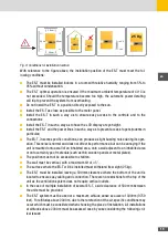
Страница 10: ...10 3 2 Function Fig 2 Function of ES T ...
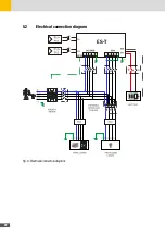
Страница 22: ...22 5 2 Electrical connection diagram ES T Fig 6 Electrical connection diagram ...
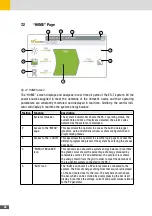
Страница 74: ...74 Fig 52 Login page The HOME page will appear Fig 53 HOME page ...


