background image

- 49 -

- 49 -

Sequence of 18 runs

For use with 4-meter seed driller and 18-meter seed spread-

er. (2+2 left outlets will close on runs 3 and 16 and, 2+2 right 

outlets will close on runs 7 and 12).  At the beginning of run 1, 

it is necessary to turn right at the end of the first road.

NOTE:

 TO RUN LEFT AT THE END OF THE FIRST 

ROAD, MOVE THE MARKER FORWARD UNTIL 

NUMBER 10 BEFORE START SOWING.

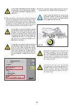
The monitor will whistle on the road-marking run.

27 metres

6 m

4 runs for 27-meter seed spreaders

1 2 3 4 5 6 7 8 9 10 11 12 13 14 15 16 17 18 1

O/P2

(R/H)

O/P1

(L/H)

O/P2

(R/H)

O/P1

(L/H)

18 runs for 6-meter seed drillers

Fig. 8.13

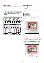
Select the type of sequence

1-  

Select the  

 channel.

2-  

Push 

 entering into mode 1. 


After 5 seconds, the first two digits flash indicating the 

type of sequence:

‘SY’ 

= Symmetrical

‘AL’ 

= Asymmetrical left

‘AR’ 

= Asymmetrical right

‘AS’ 

=  Special asymmetrical with 10 and 18 sequences.

3-  

Keep at the same time  

 and 

 for modifying the 

sequence.

Fig. 8.14

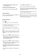
Select the sequence of runs

1-  

Push 

 and release for choosing between 

the type of sequence and the sequence of runs. 

The third and fourth digits indicate the sequence of runs.

2-  

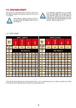
Push 

 and hold for choosing between sequence 1 

and 15.:

Fig. 8.15

Fig. 8.15

Содержание A-6000 SM

Страница 1: ...A 6000 SM NS PLUS WWW SOLAGRUPO COM Trailed pneumatic seed drill MAINTENANCE AND DOSAGE STARTING MANUAL ...

Страница 2: ...conditions They are provided with easy to use and efficient devices SOLÁ machines perform excellently with only minimum operator maintenance This manual will help you use your SOLÁ product with the upmost efficiency 2nd Edition July 2019 Ref CN 811060 GB Created by Maquinaria Agrícola Solà S L It is forbidden to copy any part of this manual Specifications are subject to change or modification with...

Страница 3: ...NTS 21 6 1 MACHINE LEVELLING 21 6 1 1 TOW BAR AND TRACTOR LEVELLING 21 6 1 2 SOWING EQUIPMENT LEVELLING 22 6 2 DEPTH CONTROLS 22 6 2 1 DEPTH TINES 22 6 2 2 DEPTH CONTROL WHEELS 23 6 2 3 COULTERS 23 6 2 3 1 SM MODEL 24 6 2 3 2 NS PLUS MODEL 25 6 3 DOSAGE 25 6 3 1 VOLUMETRIC DISPENSER 26 6 3 1 1 NORMAL SEEDS N position 26 6 3 1 2 SMALL SEEDS F position 27 6 3 2 ROLLER DISPENSER 28 6 3 3 DISPENSERS F...

Страница 4: ...INE ALARM C4 50 8 7 DISTRIBUTOR SHAFT C5 50 8 8 HOPPER LEVEL ALARM C6 51 8 9 TOTAL SEEDING CUT OFF OPTIONAL 51 8 10 EXIT CLOSING AT FOLDING PARTS OPTIONAL 52 9 MAINTENANCE 53 9 1 SERVICE FREQUENCY 54 9 2 SEED DRILLER CLEANING 55 9 3 TYRE PRESSURE 55 9 4 LUBRICATION AND GREASING 56 10 DOSAGE CHART 57 10 1 SEED CHART 57 10 2 ROLLER DISPENSER CALIBRATION FACTOR TABLE 59 10 3 TABLES FOR CONVENTIONAL O...

Страница 5: ...nance inspection and technical assis tance and transport For your safety please follow these technical safety instruc tions as SOLÀ will not be responsible for damages caused by not observing the information provided In the first chapters you will find the Technical Characteris tics and Safety Instructions as well as some essential sowing concepts Basic concepts that are required to operate the ma...

Страница 6: ...id at high presure This can inflict serious injuries with potentially fatal consequences if it passes through the skin and into the body Keep the hose lines in good condition Risk of serious physical injuries Never stand under track markers or in their ope rational area Risk of serious physical injuries Do not insert your hand into the hopper while the drive wheels are turning Risk of serious in j...

Страница 7: ...e that the danger zone surrounding the machine is clear Never leave the tractor s driver s seat while the machine is in operation Do not deposit external elements inside the hopper When mantaining the hydraulic system of the seed driller make sure that it is depressurised and the tractor s engine is off Please regularly check the condition of the tubes and hosepipes in the hydraulic system These p...

Страница 8: ...I BLE DAMAGES DURING TRANSPORTATION OR MISSING PIECES ONLY THE IMMEDIATE REPOR TING OF THIS TO THE DELIVERER WILL RESULT IN COMPENSATION WARNING SEE SECTION 3 2 TECHNICAL CHARACTERISTICS FOR KNOWING THE LOAD THAT THE BRIDGE CRANE SHALL SUPPORT The images show the towrope arrangements and mooring points for this operation Front A towrope located at the internal front part of the hopper Fig 2 2 Rear...

Страница 9: ...ERS DISTANCE BETWEEN COULTERS cm HOPPER CAPACITY litres ESTIMATED WEIGHT kg WHEELS 600 37 SM 16 5500 4600 560 45R22 5 700 43 SM 16 5500 5000 560 45R22 5 600 43 NS PLUS 14 5500 4500 560 45R22 5 600 48 NS PLUS 12 5 5500 4550 560 45R22 5 700 48 NS PLUS 14 6 5500 4700 560 45R22 5 MACHINE TYPE AND OF COULTERS MINIMUM POWER CV WORK WIDTH m TRANSPORT WIDTH m MAXIMUM HEIGHT m LENGTH m 600 37 SM 150 6 3 3 ...

Страница 10: ...ed driller has been designed for sowing of ce reals and other kind of grain seeds The machine has been designed for being dragged by an agricultural tractor If the machine is damaged due to other uses than the above the manufacturer will not be held responsible see section 11 WARRANTY All legal provisions relating to machine safety traffic and health and safety at work shall be respected The chang...

Страница 11: ...or 4 approx Regular rooting 3 cm in width and 5 cm in depth More grain per square meter is necessary to ob tain the same sprigs as in the first case Too deep sowing from 8 to 10 cm Fig 4 3 Fig 4 3 Rhizome Rhizome Seed Seed Tillering Tillering node node Very thin stem Not tiller ing and one leaf Grain reserves exhaust in a large rhizome that the ice can easily cut Poor rooting 1 cm in width and 3 c...

Страница 12: ...nd all its components the type of ter rain and the seed 5 1 COUPLING THE SEED DRILLER TO THE TRACTOR The A 6000 seed driller is fitted with a rotating shaft ring hook MAKE SURE THAT NOBODY AND NOTHING IS BETWEEN THE TRACTOR AND THE SEED DRILL ER WHEN COUPLING AND UNCOUPLING THESE PROCEDURES REQUIRE PAYING MAXI MUM ATTENTION TO AVOID DAMAGE TO THE OPERATOR MACHINE COUPLING AND UNCOUPLING PRO CEDURE...

Страница 13: ...LY The machine has electrical connections for SIGNALLING LIGHTS and WORK LAMPS CONNECTION TO ISOBUS depending on the model WORK LAMPS The machine has swivelling work lamps located at the rear of the frame Press the button to turn the lamps on or off Fig 5 2 Fig 5 2 Fig 5 2 SIGNALLING LIGHTS All models have a 7 pin connector for the signalling lights Layout and table of the 7 pin connector accordin...

Страница 14: ...NTO THE TRACTOR PTO ALWAYS HANDLE THE TRANSMISSION WITH THE ENGINE OFF ALWAYS WORK WITH THE TRANSMISSION PROTECTED AND IN GOOD CONDITIONS AVOID ANY ROTATION IN THE TRANSMISSION PROTECTION TUBE BY FIXING IT WITH THE CHAIN 2 Determine the minimum shift length L Fig 5 3 By lif ting and lowering the hydraulic lift Fig 5 3 3 Cut the plastic and metal surplus parts with the same size and reassembly the ...

Страница 15: ...a ble to star the operation with the regulator almost closed for preventing fast unfolding that may cause damage to the seed driller Fig 5 6 Fig 5 7 OPEN CLOSED For machine versions with track eraser this element can be excluded with the stopcock Fig 5 7 placed between the hopper and the seed drill See the stopcock positions in the images being OPEN for including the track eraser and CLOSED for ex...

Страница 16: ...RATED THE MACHINES COULD NOT MEET THE REQUIREMENTS STABLISHED BY THE LAW TO TRANSPORT THEM ON PUBLIC ROADS THE COMPLIANCE OF THE LAW IS STRICTLY RESPONSIBILITY OF THE FINAL USER OF THE MACHINE MAQUINARIA AGRÍCOLA SOLÁ S L DENIES ANY RESPONSIBILITY DERIVED OF NON COMPLIANCE OF THE REGULATIONS ON THE COUNTRIES WHERE THEIR PRODUCTS ARE DESTINED TO IMPORTANT THE OFFICIALLY APPROVED HOOKS FOR TRAVELLIN...

Страница 17: ...he end of its trajectory Then move it until it reaches the vertical position and the stop end Fig 5 15 4 Remove the fastening rubber bands of the canvas Fig 5 16 Fig 5 16 Fig 5 15 5 Take the handle at the ladder side Fig 5 17 and place it at the end of the canvas Fig 5 18 Turn the handle for re moving the canvas Fig 5 19 Fig 5 17 Fig 5 17 Fig 5 19 Fig 5 18 IF THE CANVAS CANNOT BE REMOVED MAKE SURE...

Страница 18: ...ut Fig 5 22 Fig 5 22 IF SEEDS DO NOT FALL MAKE SURE THAT THE SEED DISPENSED TAP IS OPENED Fig 5 22 5 6 SUPPORT FEET The machine is fitted with a hopper support foot see sec tion 5 6 1 FRONT SUPPORT FEET and two feet for the sowing equipment see section 5 6 2 REAR SUPPORT FEET LIFT THE SUPPORT FEET BEFORE OPERAT ING THE MACHINE IF THE SUPPORT FEET ARE DOWN DURING OPERATION THE EQUIPMENT MAY BE DAMA...

Страница 19: ...crank with the chain Fig 5 24 For LIFTING the support foot 1 Remove the crank fastening chain 1 Fig 5 24 and the security pin 2 Fig 5 24 2 Lift the support foot up to reaching the horizon tal position Fig 5 23 and place the security pin 2 Fig 5 23 3 Place the crank fastening chain 1 Fig 5 23 5 6 2 REAR SUPPORT FOOT Fig 5 25 Fig 5 25 B A The rear support feet are locat ed in the sowing equipment Fo...

Страница 20: ...f any seed and fertilizer Wash the machine with compressed air particularly the containers used for chemical products see section 9 2 SEED DRILLER CLEANING Verify that the machine components are in good condition Substitute the worn components Remove any particle that may produce corrosion If neces sary paint these areas with anticorrosive paint or varnish Grease and lubricate the indicated parts ...

Страница 21: ...POINT AT THE LOWEST POSSIBLE POSITION THERE FORE PLACE THE BOLT AND THE SECURITY PIN ABOVE THE PISTON ROD B1 By modifying the TRAJECTORY LIMITING STOPS at the hopper 1 the towing hook point in the seed driller to the tractor will go up or down In order to do so it is necessary to 1 Plug in the hydraulic circuit connectors of the machine to the tractor distributor Fig 6 1 2 1 A B 2 Apply pressure t...

Страница 22: ...6 2 1 DEPTH CONTROL WHEEL see section 6 2 2 COULTERS see section 6 2 3 6 2 1 DEPTH TINES The main tines determine the sowing depth A Fig 6 4 both must be adjusted at the same depth The tines are lo cated in the rear part of the machine They are adjusted by means of a pawl Once the tines are adjusted the pawls must be kept so that they do not interfere with the folding and unfolding process of the ...

Страница 23: ... wrench and clock the wheel with the fastening handle WHEN SOWING ON LOOSE AND SOFT SOIL PLACE ONE OR TWO LATERAL WHEELS LESS IN ORDER TO COMPENSATE THE WHEEL SINKING ON THE TERRAIN ADJUST THE WHEELS TO THE POSITION 2 OF THE SCALE FOR REGULAR SOWING ADJUST BOTH WHEELS AT THE SAME HEIGHT 6 2 3 COULTERS The seed drill is fitted with coulters for opening furrows in which the seeds or fertilizer will ...

Страница 24: ...ut Fig 6 8 2 1 FIXED HEIGHT ADJUSTABLE COULTERS These coulters are aligned with the wheels of the tractor and seed drill IMPORTANT IT IS ADVISABLE TO ADJUST THE SE COULTERS IF THE RUTS ARE VERY DEEP Adjust the spring nut to set the pressure exerted by the coul ter on the soil 1 Fig 6 9 THESE COULTERS HAVE A DUAL SPRING REMO VETHE INNER SPRINGTO REDUCE SUBSTANTIA LLY THE PRESSURE EXERTED BY THE COU...

Страница 25: ...2 Fig 6 11 These coulters are fastened to the bracket by a special SOLÀ bolt 3 Fig 6 11 with a self locking nut This nut is used to set the coulter clearance ADJUSTABLE 3 1 4 Fig 6 11 2 These coulters depth can be adjusted individually enabling the coulters to be lowered to adjust their height as follows 1 Adjust the nut and bolt 4 Fig 6 18 2 Place the coulter in the desired position 6 3 DOSAGE De...

Страница 26: ... TURN AND THAT THE HOPPER IS EMPTY IMPORTANT POSITION THE TURBINE AIR REG ULATOR Fig 6 15 ACCORDING TO THE SEED TO BE USED NORMAL N POSITION SMALL PO SITION Fig 6 15 F N 6 3 1 1 NORMAL SEEDS N position Follow the following steps for sowing with NORMALSEEDS Fig 6 16 3 2 4 Fig 6 18 8 9 Fig 6 17 F N 1 Remove the locking ring 3 Fig 6 16 as shown in the ima ge 2 Place the bolt 2 Fig 6 16 as shown in th...

Страница 27: ...6 19 5 Place the turbine air regulator in F position Fig 6 20 6 Pull the gear 8 Fig 6 21 until releasing it from the gear 9 Fig 6 21 and fit it to the gear 10 Fig 6 21 THE MICRO DOSAGE SYSTEM ALLOWS BETTER DISTRIBUTING SMALL AND NORMAL SIZED SEEDS IN REDUCED AMOUNTS READ THE ADVISABLE VALUE FOR SMALL SEEDS WITH THE F MICRO DOSAGE SYSTEM IN THE DOSAGE CHARTS SEE SECTION 10 CHECK THE CLEANING BRUSH ...

Страница 28: ... VERY LOW DOSES Fig 6 24 HIGH DOSE HIGH DOSE MEDIUM DOSE MEDIUM DOSE LOW DOSE LOW DOSE VERY LOW DOSE VERY LOW DOSE Fig 6 24 Follow these steps to set the quantity of sectors to adjust the dispenser to the desired dose 1 Remove the pin R Fig 6 25 2 Remove the two knobs Fig 6 26 3 Remove the side piece Fig 6 27 and take out the roller Fig 6 28 Fig 6 25 Fig 6 25 Fig 6 26 Fig 6 26 Fig 6 27 Fig 6 27 Fi...

Страница 29: ...ECTION 6 5 2 MODELS WITH ISOBUS ELEC TRICAL TRANSMISSION TO DETERMINE THE NUMBER OF SECTORS TO MOUNTS 4 SECTORS 1 SECTOR Fig 6 30 5 Reassemble the roller the side piece and fasten with the two knobs MAKE SURE THAT THE SEEGER RINGS ARE PRO PERLY MOUNTED IN THEIR HOUSINGS BY TUR NING EACH RING DO NOT FORGET THE PIN R WITHOUT IT THE DISPENSER WILL NOT WORK Fig 6 31 Fig 6 31 6 3 3 DISPENSERSFORFERTILI...

Страница 30: ... IN THE DOSAGE TABLES ONE DISPENSER SHOULD BE OVERRIDDEN IN THIS CASE THE VALUE GIVEN IN THE TABLE SHOULD BE DIVIDED BY 2 IMPORTANT IT IS NOT POSSIBLE TO OVERRIDE ANY DISPENSER FOR MODELS WITH ELECTRI CAL TRANSMISSION ISOBUS IMPORTANT IF THE SOWING EQUIPMENT HAS TWO DISTRIBUTION HEADS IT WILL NOT BE POSSIBLE TO OVERRIDE ANY DISPENSERS IN ADDITION BOTH DISPENSERS MUST BE SET TO THE SAME VALUE For m...

Страница 31: ...ating pow er is variable and dependant on multiple factors It is exper imentally calculated to be between 70 and 80 which is practically equivalent to multiplying the number of grains to be sown by 1 43 or 1 25 respectively PLEASE NOTE THAT IN SPRING TILLERING IS ALWAYS LOWER AND THEREFORE THE SEED AMOUNT TO BE SOWN SHALL INCREASE MAQUINARIA AGRÍCOLA SOLA S L RECOM MENDS THE FARMER TO SEEK PROFESS...

Страница 32: ...ERFORM A SECOND CHECK CONTROL AFTER HAVING DISTRIBUTED APPROXIMATELY THE CONTENT OF THREE HO PPERS 6 5 1 MODELSWITHMECHANICALTRANSMISSION A series of previous steps must be performed for carrying out the test 1 Couple the machine to the tractor in a slightly raised posi tion the sowing equipment does not touch the ground 2 Fill the product hoppers or partitions 3 Open the cover of the Venturi inje...

Страница 33: ...t 7 of this section AFTER TURNING THE WHEELS TURN ON THE TURBINE FOR A FEW SECONDS TO COLLECT THE PRODUCT REMAINING IN THE PRODUCT TRANSPORT PIPES 10 After turning the wheel the required number of times collect the microgranulate fertilizer Subsequently re connect the transmission for the seed dispensers 11 Accurately weigh the collected products 12 MULTIPLY by 40 the result of the weigh to obtain...

Страница 34: ...T THE DESIRED LEVEL 6 5 2 MODELSWITHISOBUSELECTRICALTRANS MISSION Aseriesofstepsmustbetakenbeforeperformingthetest 1 Couple the machine to the tractor in a slightly raised posi tion the sowing equipment does not touch the ground 2 Close the dispensers guillotine door removing a bolt that fixes the door s position Fig 6 41 Fig 6 41 Fig 6 41 3 Fill the product hopper 4 Open the cover of the Venturi ...

Страница 35: ...T MUST BE DISCONNECTED FROM THE COLLECTION BOXES IN ORDER TO PERFORM THE CALIBRATION TEST Fig 6 46 POINTING THE PIPE TOWARD A BAG OR CON TAINER Fig 6 46 Fig 6 46 x2 8 To continue with the calibration see the ISOBUS manual su pplied with the machine see the section PERFORM THE CA LIBRATION TEST Where you must enter the following values Fig 6 47 OPERATING SPEED Km h RATE dose Kg Ha CALIBRATION FACTO...

Страница 36: ...ILL NEED TO REMOVE SECTORS FROM THE ROLLER OR CHANGE THE SECTOR TYPE THEN CHANGE THE CALIBRATION FAC TOR TO THE NEW SETTING SEE SECTION 10 2 ROLLER DISPENSER CALIBRATION FACTOR TA BLE Fig 6 48 Fig 6 48 CALIBRATION TEST Dispenser Operating speed Rate Calibration factor g turn Speed min max 1 Start 10 With the controller settings made Hold down the cali bration button Fig 6 49 to start the calibrati...

Страница 37: ... instance very uneven or soft terrain or low pressured wheel etc an ex perimental test can be performed to determine the ACTUAL AMOUNT OF ROTATIONS in the TRANSMISSION WHEEL Fig 6 52 1 With a measuring tape mark the metrical distance in the plot as indicated in the following chart MACHINE TYPE METERS TO COVER 600 41 7 700 35 7 2 Mark the wheel for facilitating adding the amount of rota tions along...

Страница 38: ...r is fitted with track eraser coulters that can be adjusted in height for erasing the tractor marks The track markers can be eliminated To do so before lowering the sowing equipment to the ground adjust the stopcock placed in the hopper rear part see figure 54 The track eraser coul ters height can be modified for modify ing the depth adjust the fastening screws vertically move the coulters and fix...

Страница 39: ...VERY IMPORTANT THE COMPACTING RO LLER CANNOT BE USED ON ROUGH LAND OR SLOPES AS THIS COULD DAMAGE THE MACHI NE Fig 6 58 YOU MUST FIRST MOVE BACK THE HARROW TO DISCONNECT THE ROLLER Fig 6 58 When the roller is raised to disconnect it the harrow must be moved back following these steps 1 Loosen the nut Fig 6 59 Fig 6 59 2 Remove the bolt and the nut Fig 6 60 Fig 6 60 3 Repeat this procedure for the ...

Страница 40: ... DISC AND THE OUTER COULTER B Fig 57 follow the following formula B Ax OFCOULTERS 1 C 2 WHERE A distance between coulter centre B horizontal distance between the disc and the outer coulter C width of tractor trajectory B DISTANCE CALCULATED WITH THE PREVIOUS FORMULA IS THE ADJUSTMENT LENGTH UN TIL THE LEFT WHEEL CENTRE OF THE TRACTOR FIG 57 PERFORM THE CALCULATION USING MEASURE MENTS IN CENTIMETRE...

Страница 41: ...with the chassis two adjustable stops allow adjusting the drop angle Fig 6 65 A 1 Loosen the 2 fixing nuts A Fig 6 65 2 Remove the 2 screws 3 Move the stop until the desired position 4 Introduce the 2 screws and fix them with the 2 nuts A Fig 6 65 IN NORMAL SOWING CONDITIONS IT IS ADVI SABLE TO LEAVE THE FOLDABLE PARTS SLIGHT LY DOWNWARDS IN ORDER TO GETTING ADAP TED TO THE TERRAIN IRREGULARITIES ...

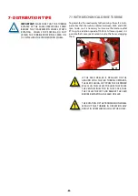
Страница 42: ...en 4200 and 4500 rpm to do so it is necessary to increase the tractor outlet PTO up to a rotation speed of 1000 m At lower speed it is possible that some seeds remain inside the hoses clogging them Fig 7 1 IF THE SEED DRILLER IS DRAGGED ON THE GROUND WITH THE AIR TURBINE UPWARDS THE SEEDS GOING OUT FROM THE DISPENSER WILL CLOG THE COLLECTOR HOSE THAT FEEDS THE VENTURI INJECTOR IN THAT CASE TAKE TH...

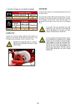
Страница 43: ...is controlled by adjusting the tractor hydraulic outlet To guaranty the seed supply to the sowing shoes it is indis pensable that the turbine rotates between 4200 and 4500 rpm according to the previous chart At lower speed it is possible that some seeds remain inside the hoses clogging them IF OIL GETS TOO HOT BECAUSE THE FLOW PUMPED BY THE TRACTOR IS EXCESSIVE OR THE OIL RESERVOIR IS TOO SMALL AN...

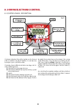
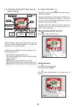
Страница 44: ...ifferent channels or readings and 3 sit uation indicating arrows C1 indicates the running speed in m sec C2 indicates two different hectares for instance a partial one and a total one C3 unable C4 indicates the turbine rotational speed in rpm C5 indicates the distributor shaft rotational speed in rpm C6 indicates when the seed level in the hopper is too low By default the reading shown on the disp...

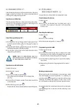
Страница 45: ...r counts the sensor impulses 5 When finishing press again The monitor has already memorized the amount of impulses 8 3 TOTAL AREA SEED DRILLER WIDTH C2 It is possible to mark two total and independent areas Visualization of total area 1 Select canal 2 2 Push to see the total area 1 and total area 2 tot 1 and tot 2 The screen will show tot 1 at first and then its value in Ha Resetting the total are...

Страница 46: ...tares for instance a partial one and a total one C3 track marker C4 indicates the turbine rotational speed in rpm C5 indicates the distributor shaft rotational speed in rpm C6 indicates when the seed level in the hopper is too low 8 5 ROAD TRACKING C3 The display shows the symbol after 10 seconds unless Total Area is selected There are 5 road marking systems Symmetric mode asym metric left mode as...

Страница 47: ... in the road tracking run Fig 8 4 ROAD MARKING RUN 5 runs for 6 meter seed drillers 1 run for 30 meter seed spreaders 3 4 5 1 2 3 4 5 1 2 Fig 8 5 6 metres Left asymmetric sequence Two outlets on the left side will be closed each time the road tracker is activated The monitor will emit a whistle and the display will flash while we are in the road tracking run Fig 8 6 Fig 8 7 Road tracking Fig 8 8 ...

Страница 48: ... 10 meter seed spread er or with 8 meter seed driller and 20 meter seed spreader 2 2 left outlets will close on runs 4 and 7 and 2 2 right out lets will close on runs 2 and 9 At the beginning of run 1 it is necessary to turn right at the end of the first road NOTE TO RUN LEFT AT THE END OF THE FIRST ROAD MOVE THE MARKER FORWARD UNTIL NUMBER 6 BEFORE START SOWING 1 2 3 4 5 6 7 8 9 10 15 metres 4 ru...

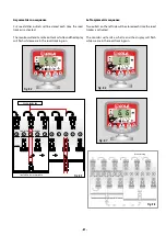
Страница 49: ... 6 7 8 9 10 11 12 13 14 15 16 17 18 1 O P2 R H O P1 L H O P2 R H O P1 L H 18 runs for 6 meter seed drillers Fig 8 13 Select the type of sequence 1 Select the channel 2 Push entering into mode 1 After 5 seconds the first two digits flash indicating the type of sequence SY Symmetrical AL Asymmetrical left AR Asymmetrical right AS Special asymmetrical with 10 and 18 sequences 3 Keep at the same time ...

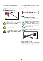
Страница 50: ... NEUMASEM PLUS WHILE THE MONITOR IS CON NECTED BY MEANS OF THE REAR SWITCH FOR ENTERING INTO PROGRAMMING MODE 2 2 PUSH THE BUTTON FOR NEUMASEM VERSIONS OR FOR NEUMASEM PLUS FOR CALIBRATING THE CHAN NEL AND GO TO CHANNEL 4 TURBINE 3 PUSH FOR MODIFYING THE FLASHING DIGIT AND KEEP PUSHING FOR MODIFYING ITS VALUE IT MUST AL WAYS BE 2 4 STOP PUSHING FOR GOING BACK TO THE NORMAL POSI TION 8 7 DISTRIBUTO...

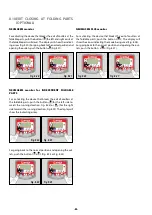
Страница 51: ...NAL NEUMASEM monitor For closing the seed outlet push the button the screen shows the flashing text CORT Fig 8 16 For going back to the normal operational position and open ing the outlets push the button The display shows the flashing text OPEN Fig 8 17 NEUMASEM Ha 0 0 1 Fig 8 16 NEUMASEM Ha 0 0 1 Fig 8 17 NEUMASEM PLUS monitor For closing the seed outlet push the button the screen shows the indi...

Страница 52: ... coulters at the foldable parts push the button for the left side to wards the running direction Fig 8 22 or for the right side towards the running direction Fig 8 23 The display will show the indicating arrow NEUMASEM Ha 0 0 1 Fig 8 22 NEUMASEM Ha 0 0 1 Fig 8 23 For going back to the normal position and opening the out lets push the button o Fig 8 24 or Fig 8 25 NEUMASEM Ha 0 0 1 Fig 8 24 NEUMASE...

Страница 53: ...into account the following factors Machine maintenance and repair must be carried out in flat and compact ground with the tractor off and the key out of the ignition contact The chosen lifting device must be adequate for the tasks to be performed Make sure of complying with the security standards Use the necessary personal protection equipment for each task to perform If using compressed air for c...

Страница 54: ...ers dust etc inside the dispenser or the pneumatic circuit Accumulation of re mainders may damage the pneumatic system SEASON END Dully wash the machine with compressed air make sure that no seed fertilizers or any other product remain inside the hopper distributor and hoses Specially wash the parts in contact with chemical products Dully lubricate the movable parts of the machine see sec tion 9 4...

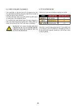
Страница 55: ... foreign object out and verify that it has not causes any damage WHENEVER YOU CLEAN THE MACHINE WITH COMPRESSED AIR USE THE CORRESPONDING PERSONAL PROTECTION EQUIPMENT PPE SEE SECTION 9 MAINTENANCE 9 3 TYRE PRESSURE Control the tyre pressure before using the seed driller WHEEL DESCRIPTION AIR PRESSURE bar 560 45 R22 5 FLOTATION WHEEL 3 3 4 00 8 TRANSMISSION wheel 2 1 18x7 8 14PR DEPTH CONTROL whee...

Страница 56: ...RATION SEE SECTION 9 1 FREQUENCY OF INTERVEN TIONS NEVER LUBRICATE THE SEED OR FERTILIZER DISPENSER SOME GREASING POINTS MUST BE GREASED AFTER 20 OR 50 OPERATION HOURS THE NON COMPLIANCE WITH THESE NORMS MAY DAMAGE THE MACHINE USE SOLID CALCIUM GREASE IN GREASING POINTS GREASE the following points Track markers Bushes in flotation transmission and depth con trol wheels Joints Transmission componen...

Страница 57: ...1 6 18 16 32 8 24 8 36 4 18 13 58 6 78 17 5 14 46 7 15 19 25 9 58 10 16 5 09 15 83 7 94 20 16 51 8 24 21 79 10 94 12 02 5 94 18 18 9 09 22 5 18 66 9 33 24 14 12 02 13 58 6 78 19 54 9 76 25 20 72 10 26 24 92 12 51 14 76 7 39 20 91 10 46 MICRO 7 METRES SMALL SEED COLZA RED CLOVER HERB TURNIP SPEC WEIGHT Kg L 0 65 0 77 0 39 0 7 Gauge Pos SMALL SEED kg ha 2 5 1 66 0 83 1 77 0 90 1 98 0 94 5 3 53 1 77 ...

Страница 58: ...291 322 310 100 320 305 287 214 323 332 305 339 327 105 335 321 302 226 339 350 321 358 345 110 352 337 317 236 358 367 337 374 362 7 METRES NORMAL SEED WHEAT RYE BARLEY OAT EDIBLE BEAN PEAS LUPINE CAROB CORN HERB WEIGHT SPEC Kg L 0 77 0 74 0 68 0 5 0 85 0 81 0 76 0 83 0 79 0 36 Pos Gauge NORMAL SEED kg ha 5 10 26 0 26 0 25 0 18 4 17 6 16 6 21 8 25 0 6 2 15 39 5 38 4 37 4 26 8 32 2 31 2 35 3 39 5 ...

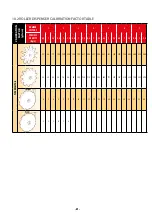
Страница 59: ...VITY Kg L 0 8 1 1 2 0 8 1 1 2 0 8 1 1 2 0 8 1 1 2 0 8 1 1 2 0 8 1 1 2 0 8 1 1 2 TIPO DE SECTOR 51 64 77 103 129 154 154 193 231 206 257 308 257 321 386 308 386 463 360 450 540 28 35 42 56 70 84 84 105 126 112 140 168 140 175 210 168 210 252 196 245 294 4 5 6 8 9 11 11 14 17 15 19 23 19 24 28 23 28 34 27 33 40 2 2 3 4 5 6 ...

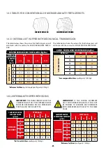
Страница 60: ...6 183 180 Reference fertilizer specific gravity 1 056 kg L 10 3 TABLES FOR CONVENTIONAL OR MICROGRANULATE FERTILIZER KITS CONVENTIONALFERTILIZER CONVENTIONALFERTILIZER MICRO FERTILIZER MICRO FERTILIZER 10 3 1 INTERNAL KIT HOPPER WITH MECHANICAL TRANSMISSION The table below shows the values that both dispensers will distribute with the sectors for MICROGRANULATE FERTILI ZER DISPENSERS MICRO FERTILI...

Страница 61: ... 61 61 ...

Страница 62: ... 62 62 ...

Страница 63: ... 63 63 ...

Страница 64: ...WWW SOLAGRUPO COM MAQUINARIA AGRÍCOLA SOLÁ S L Ctra de Igualada s n 08280 CALAF Barcelona España Tel 0034 93 868 00 60 Fax 0034 93 868 00 55 ...

Отзывы:

Похожие инструкции для A-6000 SM