- 40 -
- 40 -
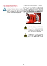
6.10 HYDRAULIC TRACK MARKERS
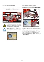
Track marker coulters are adjustable in:
-
LENGTH
, horizontal distance between the disc and the
outer element.
- Disc
ORIENTATION
, penetration angle.
Fig. 6.62
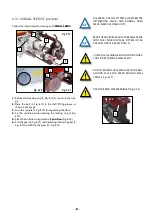
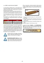
KEEP THE HYDRAULIC HOSE LINES IN GOOD
CONDITION. THE PRESSURE OIL CAN PENETRATE
THE SKIN CAUSING SERIOUS INJURIES.
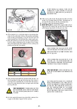
NEVER STAND WITHIN THE UNFOLDING AREA
OF THE TRACK MARKER.
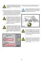
IT IS INDISPENSABLE TO FOLD THE TRACK
MARKERS WHEN TRANSPORTING THE SEED
DRILLER.
6.10.1 TRACK MARKER LENGTH ADJUSTMENT
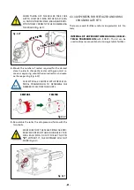
For calculating the horizontal distance BETWEEN THE TRACK
MARKER DISC AND THE OUTER COULTER (B, Fig. 57), follow
the following formula:
B
=
[
A
x
(
# OF COULTERS
+
1
)
-
C
] /
2
WHERE
:
A
= distance between coulter centre.
B
= horizontal distance between the disc and the
outer coulter.
C
= width of tractor trajectory.
B
DISTANCE CALCULATED WITH THE PREVIOUS
FORMULA IS THE ADJUSTMENT LENGTH UN-
TIL THE LEFT WHEEL CENTRE OF THE TRACTOR
(FIG. 57).
PERFORM THE CALCULATION USING MEASURE-
MENTS IN CENTIMETRES.
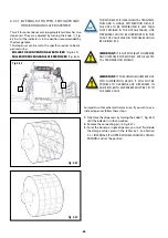
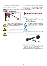
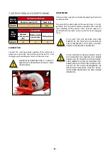
For adjusting the track marker disc distance, follow the fo-
llowing steps:
Fig. 6.63
1
1-
Loosen the 2 screws (1, Fig. 6.63).
2-
Place the track marker disc in the previously calculated B
distance (
B
= distance between the track marker and the
last sowing coulter closer to the track marker)
3-
Fix the 2 bolts (1, Fig. 6.63) when finishing the operation.

