- 25 -
- 25 -
6.2.3.2 NS-PLUS MODEL
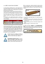
This model is fitted with two types of coulter:
FIXED COULTERS
These coulters are not height
adjustable. Consequently, the
sowing depth will be defined
by the main tines regulating
the sowing equipment’s chas-
sis (see section 6.2.1 DEPTH
TINES).
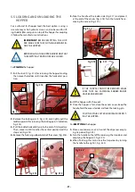
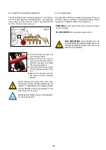
It is only possible to change the
coulters’ pressure by adjusting
the nut at bottom of the spring (1,
Fig. 6.10).
FIXED
3
1
Fig. 6.10
2
The pressure can also be adjusted by changing the bolt’s po-
sition (2, Fig. 6.10).
The coulter is fastened to the bracket by a special SOLÀ bolt
(3, Fig. 6.10) with a self-locking nut. The coulter’s side clea-
rance is adjusted using this nut.
HEIGHT-ADJUSTABLE COULTERS
These coulters are aligned with the wheels of the tractor and
seed drill.
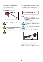
IMPORTANT:
IT IS ADVISABLE TO ADJUST THE-
SE COULTERS IF THE RUTS ARE VERY DEEP.
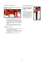
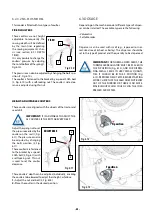
Adjust the spring nut to set
the pressure exerted by the
coulter on the soil (1, Fig.
6.11). The pressure can also
be adjusted by changing
the bolt’s position (2, Fig.
6.11).
These coulters are fastened
to the bracket by a special
SOLÀ bolt (3, Fig. 6.11) with
a self-locking nut. This nut
is used to set the coulter
clearance.
ADJUSTABLE
3
1
4
Fig. 6.11
2
These coulters’ depth can be adjusted individually, enabling
the coulters to be lowered to adjust their height, as follows:
1-
Adjust the nut and bolt (4, Fig. 6.18).
2-
Place the coulter in the desired position.
6.3 DOSAGE
Depending on the machine model, different types of dispen-
ser can be installed. The available types are the following:
• Volumetric.
• Settable roller.
Dispensers can be used with small (e.g., rapeseed) or nor-
mal-sized seeds (wheat or barley). The dispenser should be
set to the type of product and the quantity to be dispensed.
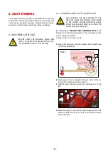
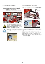
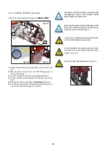
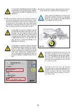
IMPORTANT:
FOR NORMAL-SIZED SEEDS, THE
TURBINE AIR REGULATOR MUST BE PLACED IN
THE N POSITION (Fig. 6.12), AND FOR DISPEN-
SING SMALL SEEDS IN VERY SMALL QUANTI-
TIES, IT SHOULD BE IN THE F POSITION (Fig.
6.13). PERFORM FIELD TESTS BEFORE STARTING
WORK. CHECK THAT THE SEED DOES NOT BLOW
OUT OF THE FURROW OR THERE IS NO MATE-
RIAL BUILDUP WHICH COULD CLOG THE COM-
PRESSED AIR SYSTEM.
Fig. 6.12
Fig. 6.12
N position
N position
Fig. 6.13
Fig. 6.13
F position
F position

