- 35 -
- 35 -
5-
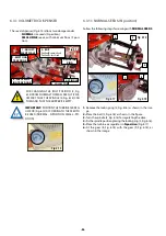
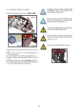
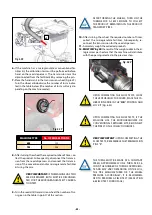
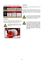
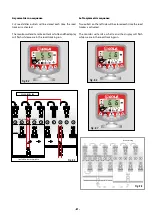
Place the supplied bag or a container underneath the
Venturi injector exit (Fig. 6.43).
Fig. 6.43
Fig. 6.43
6-
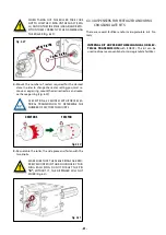
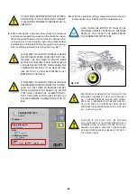
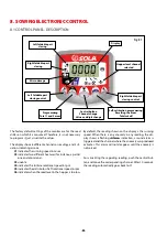
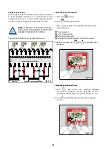
Remove the roller to identify the type and quantity of sec-
tors installed (Fig. 6.44, for removing the roller, see sec-
tion 6.3.2 ROLLER DISPENSER).
7-
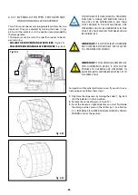
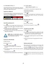
Reassemble the roller in the dispenser and place the pin in
the “R” position (Fig. 6.45).
Fig. 6.44
Fig. 6.44
Fig. 6.45
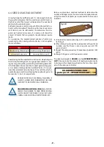
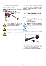
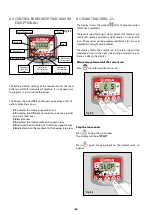
IF THE MACHINE HAS THE INTERNAL CONVEN-
TIONAL OR MICROGRANULATE FERTILIZER KIT,
BOTH PIPES OF THE MICROGRANULATE AND/
OR FERTILIZER KIT MUST BE DISCONNECTED
FROM THE COLLECTION BOXES IN ORDER TO
PERFORM THE CALIBRATION TEST (Fig. 6.46),
POINTING THE PIPE TOWARD A BAG OR CON-
TAINER.
Fig. 6.46
Fig. 6.46
x2
8-
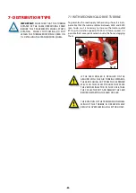
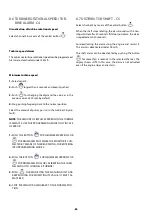
To continue with the calibration, see the ISOBUS manual su-
pplied with the machine (see the section PERFORM THE CA-
LIBRATION TEST). Where you must enter the following values
(Fig. 6.47):
- OPERATING
SPEED
(Km/h).
- RATE
(dose)
(Kg/Ha),
- CALIBRATION
FACTOR
, this value can be found from:
the specific gravity of the product to be used; the type
and number of sectors mounted in the roller (see section
10.2 ROLLER DISPENSER CALIBRATION FACTOR TABLE).
Fig. 6.47
Fig. 6.47
CALIBRATION TEST.
Dispenser
Operating speed
Rate
Calibration factor
g/turn
Speed
min.
max.
1. Start

