


-
45
-
No.JXC
※
-OMU0030-A
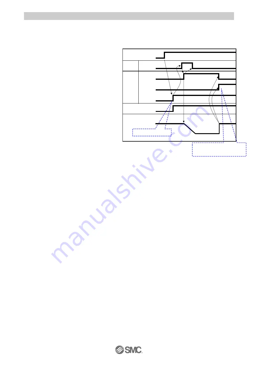
9.2 Operating procedure of parallel I/O
The operation procedure is shown below.
(1) Power on
→
Return to origin
- Procedure-
- Timing chart Power on
→
Return to origin -
1) Apply the power supply.
↓
2) The servo ON instruction (state in which
the motor can operate) is automatically
done inside the5 controller.
When servo
turns on normally * ALARM output turns
on.
The time to servo on differs depending on
the type of electric actuator and
conditions of use.
In case of electric actuator with lock, lock
is released.
↓
3) Turn on IN0 or IN1 input signal.
↓
4) BUSY output signal turns on.
(The electric actuator starts to drive.)
Controller speed and acceleration speed setting switches are ignored. The electric actuator moves
with the speed and acceleration of the electric actuator itself.
↓
5) BUSY output signal turns off.
(The electric actuator stops.)
OUT0 output signal turns on when turning on IN0 input signal.
OUT1 output signal turns on when turning on IN1 input signal.
↓
6) Return to origin is completed.
Power
Input
IN0 or IN1
BUSY
OUT0 or OUT1
*ALARM
External Lock
Output
Electric actuator
Return to
origin
Speed
The “*ALARM” is expressed as
negative-logic circuit.
24V
0V
ON
OFF
ON
OFF
・
・
・
・
OFF
ON
0mm/s
OUT0, OUT1, OUT2, OUT3
Output signals are all ON when
Turns on after servo on