background image

26

COMX-CORE-2610-ET Installation and Use (6806800P11E)

Introduction


Features

1.2

Features

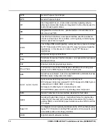
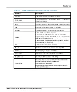
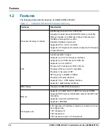
The following table lists the features of COMX-CORE-2610-ET.

Table 1-1

 COMX-CORE-2610-ET Features Summary 

Features

Description

Processor / Memory Controller

Intel Mobile processor Core i7-2610UE.

Integrated a dual channel 64bit DDR3 memory controller.

Memory capacity up to 8GB per channel, data rate up to 
1333MHz and supports non-ECC.

Integrated Graphic process unit.

Supports DX10.1, DX10, and DX9.

Supports a PCI Express x16 interface, based-on PCI Express

2.0 specifications

PCH

Intel Mobile QM67 chipset.

Supports up to 8 x1 PCI Express interfaces.

Supports up to 2 SATA 6G and 4 SATA 3G.

Supports up to 14 USB 2.0.

Provide a LPC interface for TPM, FWH etc.

Provides a SM bus, it is I2C compatible.

Provides 2 chip select of SPI.

SPI frequency is 20MHz or 33MHz.

Provides a HD audio interface.

Supports VGA + LVDS display interface.

Supports 3 digital display interfaces.

BIOS Device

One piece of 16MB SPI boot devices

Memory

Supports up to 8GB non ECC DDR3 memory per DIMM.

Supports DDR3 memory data transfer rates of 1066 MT/s and 
1333 MT/s.

Supports x8 and x16-bit DDR3 chip.

Supports 2 SODIMM.

PCI Express x16

A PCI Express x16 interface is routed to connector and it can 

be configured as:

1 PCI Express x16

2 PCI Express x8

2 PCI Express x4 plus 1 PCI Express x8

Содержание COMX-CORE-2610-ET

Страница 1: ...COMX CORE 2610 ET Installation and Use P N 6806800P11E January 2020...

Страница 2: ...to the products described therein at any time without notice SMART EC makes no commitment to update the information contained within these materials Electronic versions of this material may be read o...

Страница 3: ...Environmental and Power Requirements 33 2 1 1 Environmental Requirements 33 2 1 2 Power Requirements 33 2 2 Board Thermal Management and Placement 34 2 2 1 Board Thermal Management 34 2 3 Unpacking an...

Страница 4: ...GA LVDS LPC And Audio Interface 60 4 13 Digital Display Interface 60 4 14 Trusted Platform Module 63 4 15 SPI Flash 63 4 16 Hardware Monitor 64 4 17 Real Time Clock 64 5 BIOS 65 5 1 Overview 65 5 2 PO...

Страница 5: ...Table of Contents COMX CORE 2610 ET Installation and Use 6806800P11E 5 5 7 2 Standard Status Codes 83 A Related Documentation 89 A 1 SMART Embedded Computing Documentation 89...

Страница 6: ...6 COMX CORE 2610 ET Installation and Use 6806800P11E Table of Contents...

Страница 7: ...Installation and Removal 37 Figure 3 1 COMX CORE 2610 ET Board Layout Top view 39 Figure 3 2 COMX CORE 2610 ET Board Layout Bottom view 40 Figure 3 3 PCI Express X16 Lanes Bifurcation Configuration S...

Страница 8: ...List of Figures 8 COMX CORE 2610 ET Installation and Use 6806800P11E...

Страница 9: ...s 66 Table 5 2 Main Menu 68 Table 5 3 System Information 68 Table 5 4 Boot Features 68 Table 5 5 Advanced Menu 69 Table 5 6 Boot Configuration 70 Table 5 7 Processor Configuration 70 Table 5 8 Process...

Страница 10: ...E Table 5 27 Driver Controllers 81 Table 5 28 ACPI Wake Up Support 82 Table 5 29 Status Code Range 82 Table 5 30 Component Status Codes 83 Table 5 31 Progress Status Codes 86 Table 5 32 Architectural...

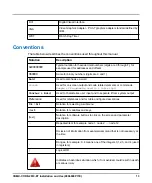
Страница 11: ...escription on page 53 describes the functions of the various components on the board Chapter 3 Controls LEDs and Connectors on page 39 provides information s on the pin assignments on the various conn...

Страница 12: ...O bus PHY Ethernet controller physical layer device Pin out Type A reference to one of five COM Express definitions for what signals appear on the COM Express module connector pins SPD Serial Presence...

Страница 13: ...t and code related elements or commands Sample of Programming used in a table 9pt Courier Bold Used to characterize user input and to separate it from system output Reference Used for references and f...

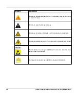
Страница 14: ...dicates a property damage message Indicates a hot surface that could result in moderate or serious injury Indicates an electrical situation that could result in moderate injury or death Indicates that...

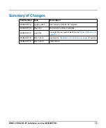
Страница 15: ...6800P11E January 2020 Rebranded to SMART EC template 6806800P11D May 2017 Re branded to Artesyn template 6806800P11C July 2012 Corrected the pin number as 204 in the System Memory on page 57 6806800P1...

Страница 16: ...16 COMX CORE 2610 ET Installation and Use 6806800P11E About this Manual...

Страница 17: ...n aircraft Only personnel trained by SMART EC or persons qualified in electronics or electrical engineering are authorized to install remove or maintain the product The information given in this manua...

Страница 18: ...modules Before installing or removing additional devices or modules read the respective documentation and use appropriate tools Operation System Damage During the course of handling shipping and assem...

Страница 19: ...omponents of the product To prevent injury from hot surfaces do not touch any of the exposed components or heatsinks on the product when handling Use the handle and face plate when removing the produc...

Страница 20: ...h a screw driver may damage the PCB or the battery holder Do not use a screw driver to remove the battery from its holder Environment Environmental Damage Improperly disposing of used products may har...

Страница 21: ...sindustrie im Zusammenhang mit Industriesteuerungen und in der Entwicklung verwendet werden Es darf nicht in sicherheitskritischen Anwendungen lebenserhaltenden Ger ten oder in Flugzeugen verwendet we...

Страница 22: ...Betrieb Sonst k nnen andere Einrichtungen die mit dem System kommunizieren besch digt werden berhitzung des Systems L ftungs ffnungen Unzureichende L ftung kann Sch den an Blades und am System verursa...

Страница 23: ...Frontblende an wenn Sie es aus dem System herausnehmen Batterie Datenverlust Wenn die Batterie nur noch ungen gend geladen ist wird der RTC zur ckgesetzt und Daten im NVRAM gehen verloren Tauschen Si...

Страница 24: ...bendreher ausbauen k nnen das PCB und die Batteriehalterung besch digt werden Benutzen Sie keinesfalls einen Schraubendreher um die Batterie aus der Halterung zu nehmen Environment Umweltverschmutzung...

Страница 25: ...10 ET provides the following interfaces to connectors for connecting with the carrier board One VGA interface One dual channel LVDS interface Three digital display interfaces Two SATA 6G interfaces Tw...

Страница 26: ...l Mobile QM67 chipset Supports up to 8 x1 PCI Express interfaces Supports up to 2 SATA 6G and 4 SATA 3G Supports up to 14 USB 2 0 Provide a LPC interface for TPM FWH etc Provides a SM bus it is I2C co...

Страница 27: ...face is routed to connector and it can be used as DP HDMI DVI SDVO 2 digital display interface are routed to connector and they can be used as DP HDMI DVI LPC A LPC interface is routed to connector SM...

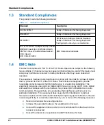
Страница 28: ...owever there is no guarantee that interference will not occur in a particular installation If this equipment does cause harmful interference to radio or television reception which can be determined by...

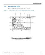
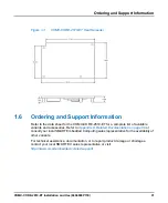
Страница 29: ...Data COMX CORE 2610 ET Installation and Use 6806800P11E 29 1 5 Mechanical Data The following figures are the top and side view of the board Figure 1 1 COMX CORE 2610 ET Mechanical Dimensions Top and...

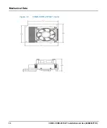
Страница 30: ...30 COMX CORE 2610 ET Installation and Use 6806800P11E Introduction Mechanical Data Figure 1 2 COMX CORE 2610 ET Cooler...

Страница 31: ...variants and accessories Refer to Appendix A Related Documentation on page 89 or consult your local SMART Embedded Computing sales representative for the availability of other variants For technical...

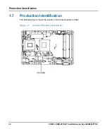
Страница 32: ...ET Installation and Use 6806800P11E Introduction Production Identification 1 7 Production Identification The following figure shows the location of the board s serial number Figure 1 4 Location of Pro...

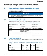
Страница 33: ...as defined in the fol lowing tables NOTICE Operating temperatures refer to the temperature of air circulation around the board but not the component temperature Table 2 1 Environmental Requirements f...

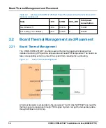
Страница 34: ...re The board can take corresponding action to protect the system from catastrophic overheating A thermal transistor is embedded in the processor The EC chip NCT7802Y can read the thermal sensor temper...

Страница 35: ...us activity and the core power is automatically shut down by the on board logic and this signal provides an indication to the carrier board 2 3 Unpacking and Inspecting the Board Verify that you have...

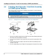
Страница 36: ...e TIM Thermal Interface Material attached at the bottom of the heat spreader or heat sink 2 Line up the heat spreader or heat sink with the four reserved mounting holes on the module 3 From the back s...

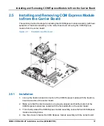
Страница 37: ...xpress module from the carrier board 2 5 1 Installation 1 Line up the board to board connector of the COM Express module with the board to board connector of the carrier board 2 Make sure that the int...

Страница 38: ...allation Removal 2 5 2 Removal 1 From the top side of the COM Express module assembly locate the five screws that connect the COM Express module assembly to the carrier board 2 Loosen and remove the s...

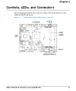
Страница 39: ...tion and Use 6806800P11E 39 Chapter 3 Controls LEDs and Connectors The following figures illustrate the location of controls LEDs and connectors on the COMX CORE 2610 ET board Figure 3 1 COMX CORE 261...

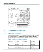
Страница 40: ...he signals from COM Express connector are based COM E SPEC2 0 standard This section describes the COM Express connector used on the board The following table lists the signals definitions Figure 3 2 C...

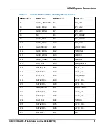
Страница 41: ...A13 GBE0_MDI0 B13 SMB_CK A14 GBE0_CTREF B14 SMB_DAT A15 SUS_S3 B15 SMB_ALERT A16 SATA0_TX B16 SATA1_TX A17 SATA0_TX B17 SATA1_TX A18 SUS_S4 B18 SUS_STAT A19 SATA0_RX B19 SATA1_RX A20 SATA0_RX B20 SATA...

Страница 42: ...I2C_DAT A35 THRMTRIP B35 THRM A36 USB6 B36 USB7 A37 USB6 B37 USB7 A38 USB_6_7_OC B38 USB_4_5_OC A39 USB4 B39 USB5 A40 USB4 B40 USB5 A41 GND FIXED B41 GND FIXED A42 USB2 B42 USB3 A43 USB2 B43 USB3 A44...

Страница 43: ...RX3 A60 GND FIXED B60 GND FIXED A61 PCIE_TX2 B61 PCIE_RX2 A62 PCIE_TX2 B62 PCIE_RX2 A63 GPI1 B63 GPO3 A64 PCIE_TX1 B64 PCIE_RX1 A65 PCIE_TX1 B65 PCIE_RX1 A66 GND B66 WAKE0 A67 GPI2 B67 WAKE1 A68 PCIE_...

Страница 44: ...LVDS_I2C_CK B83 LVDS_BKLT_CTRL A84 LVDS_I2C_DAT B84 VCC_5V_SBY A85 GPI3 B85 VCC_5V_SBY A86 RSVD B86 VCC_5V_SBY A87 RSVD B87 VCC_5V_SBY A88 PCIE0_CK_REF B88 BIOS_DISABLE1 A89 PCIE0_CK_REF B89 VGA_RED...

Страница 45: ...A106 VCC_12V B106 VCC_12V A107 VCC_12V B107 VCC_12V A108 VCC_12V B108 VCC_12V A109 VCC_12V B109 VCC_12V A110 GND FIXED B110 GND FIXED Table 3 2 COM Express Connector Pin Assignment continued PIN Numb...

Страница 46: ...D18 RSVD C19 PCIE_RX6 D19 PCIE_TX6 C20 PCIE_RX6 D20 PCIE_TX6 C21 GND FIXED D21 GND FIXED C22 PCIE_RX7 D22 PCIE_TX7 C23 PCIE_RX7 D23 PCIE_TX7 C24 DDI1_HPD D24 RSVD C25 DDI1_PAIR4 D25 RSVD C26 DDI1_PAI...

Страница 47: ...D39 DDI2_PAIR0 C40 DDI3_PAIR0 D40 DDI2_PAIR0 C41 GND FIXED D41 GND FIXED C42 DDI3_PAIR1 D42 DDI2_PAIR1 C43 DDI3_PAIR1 D43 DDI2_PAIR1 C44 DDI3_HPD D44 DDI2_HPD C45 RSVD D45 RSVD C46 DDI3_PAIR2 D46 DDI2...

Страница 48: ...61 PEG_RX3 D61 PEG_TX3 C62 PEG_RX3 D62 PEG_TX3 C63 RSVD D63 RSVD C64 RSVD D64 RSVD C65 PEG_RX4 D65 PEG_TX4 C66 PEG_RX4 D66 PEG_TX4 C67 RSVD D67 GND C68 PEG_RX5 D68 PEG_TX5 C69 PEG_RX5 D69 PEG_TX5 C70...

Страница 49: ...6 PEG_RX10 D86 PEG_TX10 C87 GND D87 GND C88 PEG_RX11 D88 PEG_TX11 C89 PEG_RX11 D89 PEG_TX11 C90 GND FIXED D90 GND FIXED C91 PEG_RX12 D91 PEG_TX12 C92 PEG_RX12 D92 PEG_TX12 C93 GND D93 GND C94 PEG_RX13...

Страница 50: ...D107 VCC_12V C108 VCC_12V D108 VCC_12V C109 VCC_12V D109 VCC_12V C110 GND FIXED D110 GND FIXED Table 3 2 COM Express Connector Pin Assignment continued continued PIN Number PIN Name PIN Number PIN Nam...

Страница 51: ...ce mount Molex 52435 2671 connector Figure 3 3 PCI Express X16 Lanes Bifurcation Configuration Switch Table 3 4 S1 Switch Configuration Switch Configuration PCIE Configuration 1 4 open 2 3 open 1x16 l...

Страница 52: ...EDs and Connectors XDP Connectors 11 HOOK1 12 HOOK2 13 HOOK3 14 HOOK4 15 HOOK5 16 VCCOBS_AB 17 HOOK6 18 HOOK7 19 GND 20 TDO 21 TRST 22 TDI 23 TMS 24 TCK1 25 GND 26 TCK0 Table 3 5 J1 XDP Debug Port Con...

Страница 53: ...l structure of the board in detail The COMX CORE 2610 ET board is designed to use with a carrier board that can provide power and I O connectors It is an extended temperature module and the temperatur...

Страница 54: ...ost Technology Two channels of DDR3 memory with a maximum of one SO DIMM per channel Memory DDR3 data transfer rates of 1066 MT s 1333 MT s and 1600 MT s The PCI Express X16 ports are fully compliant...

Страница 55: ...ports up to 14 USB 2 0 Provides a LPC interface for TPM FWH etc Provides a SM bus it is I2C compatible Provides two chip select of SPI SPI frequency is 20MHz or 33MHz Provides a HD audio interface Sup...

Страница 56: ...s device connection Figure 4 2 Board SM Bus Device Connection Diagram Device Address Device Device Description Remark A8 AT24C02C 2Kbit EEPROM Factory Data should not be modified by the customer unles...

Страница 57: ...describes the PCI Express x16 interface configuration Supplier Supplier Part Number Specifications Virtium VL47B1G63D K9SA DDR3 1333 8GB SODIMM Non ECC Virtium VL47B5663D K9SG DDR3 1333 2GB SODIMM No...

Страница 58: ...QM67 and uses 82579LM as GE PHY GLCI is the connectivity interface between QM67 and 82579LM and it occupies the PCIE port 7 NOTE The Ethernet supports LAN wake function 4 9 PCI Express Port The QM67...

Страница 59: ...upports 6G SATA interface whereas Port 3 and Port 4 supports 3G SATA interface The power supply for SATA interface is provided by carrier board 4 11 USB Interface The QM67 can support up to 14 USB2 0...

Страница 60: ...ort maximum pixel rate up to 224 MP s The LPC interface is routed to connector and can connect Super IO FWH etc It supports two Master DMA devices and supports for Security Device TPM connected to the...

Страница 61: ..._RED DDPB_ 0 P TMDSB_DATA2 DDPB_ 0 N SDVO_RED DDPB_ 0 N TMDSB_DATA2 DDPB_ 1 P SDVO_GREEN DDPB_ 1 P TMDSB_DATA1 DDPB_ 1 N SDVO_GREEN DDPB_ 1 N TMDSB_DATA1 DDPB_ 2 P SDVO_BLUE DDPB_ 2 P TMDSB_DATA0 DDPB...

Страница 62: ...DSC_DATA1 DDPC_ 2 P N A DDPC_ 2 P TMDSC_DATA0 DDPC_ 2 N N A DDPC_ 2 N TMDSC_DATA0 DDPC_ 3 P N A DDPC_ 3 P TMDSC_CLK DDPC_ 3 N N A DDPC_ 3 N TMDSC_CLK DDPC_AUXP N A DDPC_AUXP N A DDPC_AUXN N A DDPC_AUX...

Страница 63: ...er board can be used to configure the boot BIOS ROM The carrier board typically provides jumper selections or equivalent to choose the BIOS boot device Refer to the COMX CAR 612 COM Express Carrier Bo...

Страница 64: ...ation speed It implements voltage monitoring capability on 5V 1 5V 1 05V VGFX core and CPU core It can monitor the CPU temperature by the PECI signal connected to the CPU It can also monitor the board...

Страница 65: ...rror is detected the boot process is halted If possible a message is displayed but failures early on in the test can only be indicated by POST codes Viewing all checkpoints generated by Phoenix SCT fi...

Страница 66: ...pied back to this area via the Exit menu The operation of the BIOS defaults is described later in this document To start the utility you must press the F2 key during the early stages of POST after pow...

Страница 67: ...of a particular setup item For example Date and Time Tab The Tab key allows you to select fields Esc The Esc key allows you to discard any changes you have made and exit the Phoenix SCT Setup When yo...

Страница 68: ...pe memory type and size Boot Features Allows to select Power on state for NumLock Table 5 3 System Information Field Description BIOS Version BIOS version Build Time BIOS build time Processor Type CPU...

Страница 69: ...Processor Configuration Set CPU configuration Peripheral Configuration Set system peripheral configuration HDD Configuration Set hard drive and controller configuration Memory Configuration Displays...

Страница 70: ...Default setting is Disabled Table 5 7 Processor Configuration Field Description Active Processor Cores Number of cores to enable in each processor package Default setting is All Intel HT Technology Wh...

Страница 71: ...fault setting is Enabled Turbo Mode Enable processor Turbo Mode EMTTM must also be enabled Default setting is Enabled C States Enable processor idle power saving states C States Default setting is Ena...

Страница 72: ...Hard Disk 1 Display the identity of the device attached Serial ATA Port 2 Hard Disk 2 Display the identity of the device attached Serial ATA Port 3 Hard Disk 3 Display the identity of the device atta...

Страница 73: ...ogy for Directed I O VT d by reporting the I O device assignment to VMM through DMAR ACPI tables Default setting is Disabled Table 5 15 Graphics Configuration Field Description Primary Display Selecti...

Страница 74: ...is for SDVO to VGA device EFP2 is for Integrated HDMI Default setting is LFP IGD LCD Panel Type Select the video device which will be activated during POST This has no effect if external graphics are...

Страница 75: ...bled Table 5 19 SB Azalia Configuration Field Description Azalia Control detection of the Azalia device Default setting is Auto Azalia internal HDMI codec Enable Disable internal HDMI codec Default se...

Страница 76: ...additional firmware in the SPI device Default setting is Enabled Intel AMT Hot Key Enable or Disable Intel AMT Hot Key during POST to enter MEBX setup Default setting is Enabled Intel AMT Setup Promp...

Страница 77: ...r Password is Show current status of Supervisor password Setting Set User Password is Show current status of User password Setting Set Supervisor Password Press Enter to set Supervisor Password Superv...

Страница 78: ...User Authentication Prompt on boot Default setting is Disabled TPM Support This is used to decide whether TPM support should be enabled or disabled Default setting is Disabled Table 5 24 Security Menu...

Страница 79: ...Boot Menu COMX CORE 2610 ET Installation and Use 6806800P11E 79 5 5 4 Boot Menu Figure 5 4 Boot Menu...

Страница 80: ...stem automatically You can also press F10 to perform this task Exit Discarding Changes Exit the setup configure driver without saving changes You can also press F10 to perform this task Load Setup Def...

Страница 81: ...ing table lists the driver controllers compatible for this product Save Changes Save all changes of all menus but do not reset system Table 5 26 Exit Menu continued Field Description Table 5 27 Driver...

Страница 82: ...FDD ATA ATAPI ATAPI CD ATA HDD Other HDD PXE Network Boot PCI Express Ethernet Controller Internal Shell UEFI Shell 5 7 POST Codes 5 7 1 Status Code Range Table 5 28 ACPI Wake Up Support Power Button...

Страница 83: ...x25 POSTCODE_CC_HDD_PASSWORD 0x26 POSTCODE_CC_CPU_IO 0x27 POSTCODE_CC_BOOT_SCRIPT 0x28 POSTCODE_CC_STATUS_CODE 0x29 POSTCODE_CC_DATA_HUB 0x2A POSTCODE_CC_HII_DATABASE 0x2B POSTCODE_CC_RESET 0x2C POSTC...

Страница 84: ...CODE_CC_TIMER 0x3E POSTCODE_CC_PCI_BUS 0x3F POSTCODE_CC_ISA_BUS 0x40 POSTCODE_CC_IDE_BUS 0x41 POSTCODE_CC_AHCI_BUS 0x42 POSTCODE_CC_SCSI_BUS 0x43 POSTCODE_CC_USB_BUS 0x44 POSTCODE_CC_FLOPPY 0x45 POSTC...

Страница 85: ...0x56 POSTCODE_CC_LEGACY_BIOS 0x57 POSTCODE_CC_BLOCK_IO_THUNK 0x58 POSTCODE_CC_CRYPTO 0x59 POSTCODE_CC_XHCI_RESET 0xA0 POSTCODE_CC_PLATFORM_STAGE0 0xA1 POSTCODE_CC_PLATFORM_STAGE1 0xA2 POSTCODE_CC_PLAT...

Страница 86: ...ODE_CC_SERIAL_CONTROLLER Table 5 30 Component Status Codes continued Status Code Code Symbol Table 5 31 Progress Status Codes Status Code Code Symbol 0x01 POSTCODE_PC_COMP_PEI_BEGIN 0x02 POSTCODE_PC_C...

Страница 87: ...E_PC_SEC_EXIT 0xE2 POSTCODE_PC_PEI_ENTRY 0xE3 POSTCODE_PC_PEI_EXIT 0xE4 POSTCODE_PC_IPL_DXE 0xE5 POSTCODE_PC_IPL_S3 0xE6 POSTCODE_PC_S3_OS 0xE7 POSTCODE_PC_IPL_RECOVERY 0xE8 POSTCODE_PC_IPL_EXIT 0xE9...

Страница 88: ...88 COMX CORE 2610 ET Installation and Use 6806800P11E BIOS Standard Status Codes...

Страница 89: ...l documentation can be found by using the Documentation Search at https www smartembedded com ec support or you can obtain electronic copies of SMART EC documentation by contacting your local sales re...

Страница 90: ...90 COMX CORE 2610 ET Installation and Use 6806800P11E Related Documentation SMART Embedded Computing Documentation...

Страница 91: ...1...
Страница 92: ...egistered trademark of SMART Modular Technologies Inc and SMART Embedded Computing and the SMART Embedded Computing logo are trademarks of SMART Modular Technologies Inc All other names and logos refe...
Отзывы: