60 90 570 D 3485
D 3485.201.04.09.02
09.2007
23
4 Installation
båÖäáëÜ
båÖäáëÜ
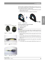
The optical fibers are supplied in nonsterile condition and wound up on the
take-up reel (see illustration below). The optical fiber can be wound onto the
take-up reel either clockwise or counterclockwise.
¾
R
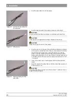
emove the end of the optical fiber with the black protective cap from the
fastening of the take-up reel.
¾
Remove the black protective cap
(A)
from the optical fiber.
Figure 12:
Take-up device
Screw on optical fiber connector with magnet.
The connector comprises 2 parts:
z
Tapered part with slot
z
Cylindrical part
NOTICE
i
The SIROLaser detects that the optical fiber is also properly connected only if
it is connected to the connector. If the connector or the optical fiber is missing,
an error message is output.
¾
A
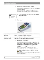
ttach the slotted optical fiber connector with magnet (see Fig. 13)
to the
optical fiber.
¾
The optical fiber must be laid in the slot of the tapered part (see Fig. 14).
¾
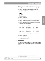
Screw on the tapered part from the rear up to the stop of the optical fiber
(see Fig. 15).
You do not have to roll up the optical fiber. The optical fiber is thus protected
against contamination.
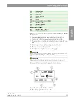
ª
The
optical fiber can now be connected to the SIROLaser (see Fig. 16).
A
Figure 13:
Connector
Cylindrical part
Tapered part with slot
Figure 14:
Optical fiber with protection
caps
Figure 15:
Optical fiber with magnet
Содержание sirolaser blue
Страница 1: ...k W MVKOMMT b pfoli l f...
Страница 57: ......


