74
Control Mode
:
P S T
Range
:
1
~
1000
Data size
:
16bit
Display mode
:
Decimal system
Parameter function
:
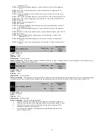
Please refer to section3.7.2.
P1-58
Frequency division output pulse
direction selection
Initail value
Unit
Communication
Address
0
-
213AH
Control Mode
:
P S T
Range
:
0
~
1
Data size
:
1bit
Display mode
:
Decimal system
Parameter function
:
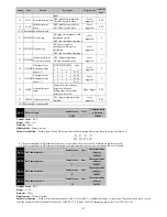
Table7-4 Output pulse feedback direction
Forward
Inversion
P1-58=0
PA+-
PB+-
A phase lead B phase 90°
PA+-
PB+-
B phase lead A phase 90°
P1-58=1
PA+-
PB+-
B phase lead A phase 90°
PA+-
PB+-
A phase lead B phase 90°
P1-60
Fault display selection
Initail value
Unit
Communication
Address
0
-
213CH
Control Mode
:
P S T
Range
:
0
~
3
Data size
:
16bit
Display mode
:
Decimal system
Parameter function
:
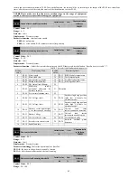
Select display which fault in the drive digital tube
P1-60=0
:
Last fault
;
P1-60=1
:
The first 1 failures
;
P1-60=2
:
The first 2 failures
;
P1-60=3
:
The first 3 failures
Servo drive a total of 4 times the recent the information failure of failure, through this function, it can choose monitoring parameters of
P0-18 ~ P0-22 to show which failure.
P1-61
System parameter initialization
Initail value
Unit
Communication
Address
0
-
213DH
Control Mode
:
P S T
Range
:
0
~
65535
Data size
:
16bit
Display mode
:
Decimal system
Parameter function
:
System parameter initialization related setting. Stop setting, power up again.
P1-61=1
:
When power up again, removal of fault record
;
P1-61=65535
:
When power up again, all function code parameters are returned to the factory default value (except PE group
)
;
P1-61=
Other values
:
No operation.
7.3 P2-xx Internal multi segment position (Pr) control parameter
This set of features can be enabled if the servo driver is currently in a position mode (P1-00=1) and the command source is an internal multi
segment instruction (P1-01=1).
P2 - xx group a total of 64 functional code, is divided into 16 groups, corresponding to the multi segment location directive PR1 to pr16. Since
the beginning of P2-00, each of the 4 functional code to set a target location, to achieve the target position allows the uniform speed, after the
positioning completion of the waiting time.
The following is a detailed description of the four parameters P2-00~P2-03 involved in the first paragraph of PR1, the other 15 sections of the
same, no longer detail. Please refer to figure 7-17.
P2-00
The number of internal position
instruction 1 pulses high five
Initail value
Unit
Communication
Address


