56
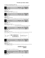
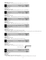
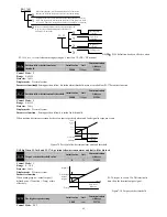
LED0
LED1
LED2
LED3
LED4
LED2, LED1,LED0 Show the current state of the servo drive
,
three states below
:
Servo is in the normal operation condition
,
LED2~LED0 display:
Servo is ready but not enabled
,
LED2~LED0 display:
Servo is in a fault state
,
LED2~LED0 display:
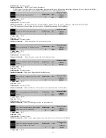
LED3 shows current control mode for servo drives
,
the decimal point indicates whether the brake resistance is in the discharge state.
Servo is in position control
mode, the brake resistance is
not working
Servo is in the position control
mode, the brake resistance is
discharged.
Servo is in the speed control
mode, the brake resistance is
not working
Servo is in the speed control
mode, the brake resistor is
discharged
The servo is in the torque
control mode and the brake
resistance is not working
Servo is in the torque control
mode, the braking resistor is
discharged.
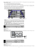
LED4 shows the direction of the current motor speed, the number of points to maintain the brake terminal (BK-) status.
Motor reversal, keeping the
brake control terminal BK is
invalid
Motor reversal, keeping the
brake control terminal BK
valid
Zero speed of motor, the
brake control terminal BK is
invalid
Zero speed of motor, the brake
control terminal BK is valid
The motor is rotating , and
the brake control terminal
BK is invalid
The motor is rotating , and the
brake control terminal BK is
valid
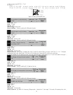
For example:
Motor
forward
Brake control
terminal valid
Braking resistor is
discharging
Torque
mode
Servo is in the
normal operation
condition.
In particular, when the servo is at the origin of the
regression process, P0-13is showing:
P0-14
Brake load ratio
Initial value
Unit
Communication
Address
0
%
000EH
Control mode
:
P S T
Data size
:
16bit
Display mode
:
Decimal system
Parameter function
:
When the motor is in the braking state, the load rate of the current braking resistor is displayed.
P0-15
IGBT module temperature
Initial value
Unit
Communication
Address
0
℃
000FH
Control mode
:
P S T
Data size
:
16bit

