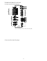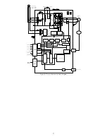
23
Signal
Pin
Default function
Default
function
number
Corresponding
function code
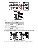
DO2
23
Brake output signal
The maximum allowable output current 40mA
2
P6-14
DO2-
38
DO3
9
Rotation of the motor output signal
The maximum allowable output current 40mA
8
P6-15
DO3-
39
DO4
24
Output signal stops servomotor
The maximum allowable output current 40mA
12
P6-16
DO4-
10
+24V
25/40 Internal 24V supply voltage range + 22V ~ 26V, 200mA maximum output
current
COM
7/22/36
COM+
21
Digital input common positive terminal
(
12V
~
24V)
4.4.3 Digital input (DI) function definition table
Input Signal Function Description
Set
value
Name
Function
Describe
Trigger
mode
Running
mode
0
Disabled Terminal invalid
1
S-ON
Servo enable
ON- Servo motor power enable
OFF- Servo motor cancel
enabled
Level
triggered
P S T
2
ALM-RST
Alarm and fault
reset
ON- If the abnormal condition
have been solved, resettable
fault can be reset.
Edge
triggered
P S T
3
P-CLR
Position control
pulse deviation
counter clear
See P1-34 for definition of
trigger
Edge / level
triggered
P
4
DIR-SEL
Speed command
direction
selection
ON- Instruction in the opposite
direction
OFF- Default command
direction
Level
triggered
S
5
CMD0
Internal
instruction bit0
When works in position control
mode, it is location
multi-segment switching
function signal;
When works in speed control
mode, it is speed multi-segment
switching function signal;
Level
triggered
P S
6
CMD1
Internal
instruction bit1
Level
triggered
P S
7
CMD2
Internal
instruction bit2
Level
triggered
P S
8
CMD3
Internal
instruction bit3
Level
triggered
P S
9
CTRG
Internal
instruction trigger
Multi- segment position trigger
condition
Edge
triggered
P
10
MSEL
Control mode
switching
Used for mixed control mode
switch
Level
triggered
P S T
11
ZCLAMP
Analog speed
command zero
fixed enable
ON- Zero fixed function
enabled
OFF- Zero fixed function
disenabled
Level
triggered
S
12
INHIBIT Pulse inhibit
ON- Prohibit command pulse
input
OFF- Allow command pulse
input
Level
triggered
P
13
P-OT
Forward driving
inhibit
OFF- Prohibit forward drive
ON- Allow forward drive
Level
triggered
P S T
14
N-OT
Reverse driving
inhibit
OFF- Prohibit Reverse driving
ON- Allow reverse drive
Level
triggered
P S T
15,16
Not used
17
Forward Jog
ON- Input in accordance with
the given instruction
OFF- Stop input running
instruction
Level
triggered
S
18
JOGCMD- Reverse Jog
ON- Input in accordance with
the given instruction
Level
triggered
S

