22
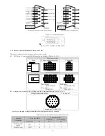
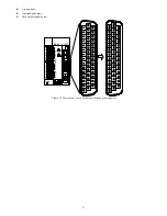
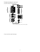
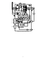
4.4.1 Control signal terminal pin distribution
Signal
Pin
Function description
PULHIP
1
The positive terminal of command pulse when using 24V power supply
DI7
2
Digital input, the default function number is 7
See section 3.4.2 and
3.4.3
DI5
3
Digital input, the default function number is 5
DI3
4
Digital input, the default function number is 3
DI1
5
Digital input, the default function number is 1
+5V
6
+ 5V power supply, maximum output current 50mA.
COM
7/22/36 Power supply ground (+ 24V)
DO1
8
Digital output, the default function number is 1
See section 3.4.2 and
3.4.4
DO3
9
Digital output, the default function number is 8
DO4-
10
DO4 digital output COM terminal
PZ+
11
Z pulse positive frequency dividing output, the maximum current is
20mA.
PB+
12
B pulse positive frequency dividing output, the maximum current is
20mA.
PA-
13
A pulse negative frequency dividing output
GND
14/29/41/4
2/43/44
Analog input signal ground
AI1
15
Analog input, input impedance: 10kΩ, the maximum input voltage ±
12V.
PULHIS
16
The positive terminal of command pulse when using 24V power supply
DI8
17
Digital input, the default function number is 8
See section 3.4.2 and
3.4.3
DI6
18
Digital input, the default function number is 6
DI4
19
Digital input, the default function number is 4
DI2
20
Digital input, the default function number is 2
COM+
21
Digital input common positive terminal
DO2
23
Digital output, the default function number is 2
See section 3.4.2 and
3.4.4
DO4
24
Digital output, the default function number is 12
+24V
25/40
Internal 24V power supply, voltage range of + 20V ~ 26V.
The maximum output current is200mA.
PZ-
26
Encoder Z pulse negative output
PB-
27
Encoder B pulse negative output
PA+
28
Encoder A pulse positive output.
The maximum current is 20mA.
AI2
30
Analog input. The input impedance is 10kΩ,
The maximum allowable input voltage is ± 12V.
SIGN+
31
Position direction c
SIGN-
32
Position direction command -
PULSE+
33
Position pulse c
PULSE-
34
Position pulse command -
OCZ
35
Encoder Z pulse open collector output.
The maximum allowable input current is 40mA.
DO1-
37
COM digital output terminal of DO1
See section 3.4.2 and 3.4.4
DO2-
38
COM digital output terminal of DO2
DO3-
39
COM digital output terminal of DO2
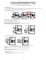
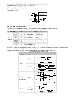
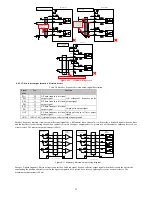
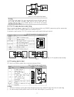
4.4.2 Digital Input \ Output Terminal Description
Signal
Pin
Default function
Default
function
number
Corresponding
function code
DI1
5
Servo motor power on enable
1
P6-02
DI2
20
Alarm fault reset
2
P6-03
DI3
4
Position control pulse deviation counter clear
3
P6-04
DI4
19
Speed instruction direction selection
4
P6-05
DI5
3
Internal instruction bit0
5
P6-06
DI6
18
Internal instruction bit1
6
P6-07
DI7
2
Internal instruction bit2
7
P6-08
DI8
17
Internal instruction bit3
8
P6-09
DO1
8
Servo ready output signal
The maximum allowable output current 40mA
1
P6-13
DO1-
37


