background image

Transceiver unit

43

851-164336 / D

5 TRANSCEIVER UNIT

Introduction

Note

The Transceiver Unit must be mounted as a complete unit, i.e. the
door should not be opened until the unit is securely fastened to the
bulkhead.

Before mounting the Transceiver Unit, observe that the distance
between the Hull Unit and the Transceiver Unit is restricted by the
flexible transducer cable joining the two. Remember to take into
consideration the slack necessary to lower the transducer.

Caution

Do not fasten the transducer cable to the Transceiver Unit until
described later in the start-up procedure.

Free bulkhead space is required to mount the Transceiver Unit
cabinet.

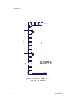
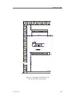
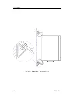
Drawing references, see pages 46, 44 and 45.

Procedure

Observe the following procedure. To ensure correct operation, tick
off every item when the action has been carried out.

1

Remove the two mounting brackets which are fastened to the
shock absorbers on the Transceiver Unit.
- Use the Allen key found in the plastic bag fastened to the

upper shock absorber.

2

Weld the mounting brackets securely to the bulkhead.

3

Use a chain fall or similar device to lift the Transceiver Unit
into position and bolt it to the mounting brackets.
- Note that eight bolts are provided in the plastic bag

fastened to the upper shock absorber.

4

Connect the grounding cable from the Transceiver Unit to
the mounting bracket.

Содержание Simrad SP70

Страница 1: ...Simrad SP70 Low frequency long range fishery sonar Installation manual A L W A Y S A T T H E F O R E F R O N T O F T E C H N O L O G Y www simrad com...

Страница 2: ......

Страница 3: ...sonar must never be powered up when the ship is in dry dock The transducer will be damaged if it transmits in open air To prevent inadvertent use of the sonar pull out the mains plug on the Sonar Proc...

Страница 4: ...nuals before attempting to operate or work on the equipment Simrad AS disclaims any responsibility for damage or injury caused by improper installation use or maintenance of the equipment Copyright E...

Страница 5: ...Page 23 3 Installation of the Sonar Trunk Page 29 4 Installation of the Hull Unit Page 34 5 Installation of the Transceiver Unit Page 43 6 Installation of Wheelhouse Units Page 47 7 Cable layout Page...

Страница 6: ...ied as the basis for the shipyard s own installation drawings applicable to the vessel On completion of the installation this manual must be kept on the vessel for reference purposes during system mai...

Страница 7: ...9 Purpose 9 Equipment responsibility 9 Receipt unpacking and storage 9 1 6 General safety rules 10 1 7 Installation requirements 11 Responsibility and approval 11 Supply power 11 Environmental require...

Страница 8: ...ir vent pipe 27 Bilge pump 27 Lighting 27 Dry docking 27 Decking 27 3 SONAR TRUNK 29 3 1 Mounting of the trunk 29 3 2 Protection 30 Protecting blister 30 Corrosion protection 30 3 3 Trunk installation...

Страница 9: ...nterface Unit 54 6 7 Loudspeaker 55 7 CABLE LAYOUT 56 7 1 Introduction 56 7 2 System cabling 57 Cable layout 57 System and shipyard cables 57 7 3 Cable specifications 59 7 4 Wheelhouse cabling 61 Intr...

Страница 10: ...witch 98 9 6 Starting up the Wheelhouse Units 100 Introduction 100 Start up 100 Display set up 101 9 7 Checking the Operating Panel 102 Introduction 102 Functional test 102 Power off 106 9 8 Checking...

Страница 11: ...eneral 130 Default interface settings 130 Changing the interface settings 130 Serial line inspection 131 10 3 Speed log 133 Introduction 133 Pulse log 200 pulses per nautical mile 133 Speed log with R...

Страница 12: ...cifications 157 12 4 Telegram formats 158 Introduction 158 NMEA 0183 159 Gyro 160 Speed log 161 Time 162 Trawl systems 163 Global Positioning System GPS 169 Echo sounder 171 Sea current sensor 173 Win...

Страница 13: ...Only minor corrections Rev C Partly reorganised Test of radio bouys introduced Additional hull units added Rev D Introduced new MC70 Sonar Processing Unit and new Sonar Interface Unit Other minor cor...

Страница 14: ...Simrad SP70 X 851 164336 D This page is intentionally left blank...

Страница 15: ...parate the victim from the source If the voltage exceeds 1000 volts switch off the supply and be ready to catch the victim Take care do not become a victim yourself Commence first aid on the spot Cont...

Страница 16: ...n for every five cycles of ECM This will be hard work but keep going His life depends on you If there are other people available to help one should perform the ECM while one performs the artificial re...

Страница 17: ...ion this document should be stored on board the vessel for later reference when updating or servicing the equipment Note The installer is responsible for the equipment during the installation The guar...

Страница 18: ...m diagram A simplified SP70 system diagram is shown Legend A Colour display B Operating Panel C Sonar Processor Unit D Sonar Interface Unit E Loudspeaker F Multiple interface lines to peripheral equip...

Страница 19: ...Introduction 3 851 164336 D CD6484B H G E A C D B F Wheelhouse Sonar room 115 230 Vac 115 230 Vac 115 230 Vac 230 380 440 Vac 3 phase Figure 1 SP70 System diagram...

Страница 20: ...cerning weights and dimensions of the various units General The Simrad SP70 sonar system is delivered without a dome system The standard hull unit employs a Simrad SQ4 installation trunk allowing the...

Страница 21: ...Specifications Order number SP71 1 2 m 25 knots 20 bolts PCD 620 mm SP7 205674 SP72 1 6 m 20 knots 20 bolts PCD 620 mm SP7 204880 SP73 1 2 m 25 knots 24 bolts PCD 680 mm SP7 205501 SP74 1 6 m 20 knots...

Страница 22: ...terface box is required Unit Order number LR40 Gyro interface unit 298 078535 90 degrees tilt The optional tilt also opens all 180 degrees vertical mode presentations Unit Order number 90 degrees tilt...

Страница 23: ...signals can be ordered from Simrad 3 phase synchro signal 20 to 150 V L L 50 60 400 Hz gear ration 1 360 or 1 180 3 phase stepper signal 20 to 150 V L L gear ration 1 360 or 1 180 Refer to page 6 for...

Страница 24: ...connected Simrad PI30 Purse seine system RS 232 Trawl system To provide trawl information on the sonar s display one of the following Simrad trawl systems may be connected Simrad FS903 Trawl sonar sys...

Страница 25: ...unpacking and storage Upon accepting shipment of the equipment the shipyard and or the dealer should ensure that the delivery is complete and inspect each shipping container for evidence of physical...

Страница 26: ...ce or installation work is being carried out on the system Read and understand the first aid instructions for electric shock For safety reasons during troubleshooting on the equipment with power ON tw...

Страница 27: ...ndently maintain power to the sonar for a minimum of 10 minutes This ensures that the system can be switched off in a controlled manner in the event of a power failure Environmental requirements Tempe...

Страница 28: ...quipment Note The location of the sonar trunk and or protection blister must be noted on the vessel s docking plan for future reference Wiring The cable from the wheelhouse to the sonar room must be s...

Страница 29: ...stigated by the packer shipper before the unit is dispatched Local transportation All local transportation must be carried out according to the same specifications as for the initial delivery In gener...

Страница 30: ...llation and use During this storage period certain specifications must be met The equipment must be preserved and stored in such a way that it does not constitute any danger to health environment or p...

Страница 31: ...n temperature must not be lower than 30 C and not warmer than 70 C If other limitations apply the crates will be marked accordingly Note Transducers must not be stored in temperatures below 20 C 3 The...

Страница 32: ...ing instructions General unpacking procedure Normal precautions for the handling transportation and storage of fragile electronic equipment must be undertaken Note Iftheunitisnottobepreparedforimmedia...

Страница 33: ...ift the unit in its bag out of the carton and place it in a stable position on the floor work bench Note Cables must never be used as carrying handles or lifting points Inspect the unit for damage bef...

Страница 34: ...nts and isolated from sources of vibration Note Do not break the seal to open a circuit board package before the board is to be used If the board package is returned to the manufacturers with the seal...

Страница 35: ...f the mechanical unit may have been exposed to a salt atmosphere while it was in use it must be thoroughly cleaned both internally and externally to prevent corrosion If the construction materials and...

Страница 36: ...iod Caution Units containing lithium or alkaline batteries must be handled separately and with care Such units are marked accordingly Do not attempt to recharge such batteries open them or dispose of...

Страница 37: ...esidue of the vaporised metal on the device and thus create a short circuit This may result in a catastrophic failure or degraded performance of the device ESD Protection during transport and storage...

Страница 38: ...mperature protection If the unit must be protected against extremes of temperature the carton cratemustbelinedonallwalls baseandlidwith5 cmthick polyurethane or polystyrene foam These units will be id...

Страница 39: ...must be taken into consideration the most important of which is the vessel s construction This guide is for use in selecting the best location for the transducer and includes a brief description of ar...

Страница 40: ...tion is off set from the vessel s centre line make sure that transducer transmission and reception will not be obstructed by the keel Welding marks for docking Waterline at normal trim LBP CD1881 1 3...

Страница 41: ...e hull indentations and pipe in outlets are potential sources of underwater noise They may act as resonant cavities amplifying noise at certain frequencies create cavitation or turbulence Transducers...

Страница 42: ...attachment point rated at a minimum of two tons for supporting a lifting device should be located above the Hull Unit This permanently installed fixture will facilitate Trunk and Hull Unit mounting an...

Страница 43: ...g cock on the Hull Unit The pipe should be laid with with continuous rise to free air on deck or through the ship s side Note Through hull modifications are subject to approval by the vessel s nationa...

Страница 44: ...0 2080 Min 3000 lifting device Heater Transceiver unit Lighting Load capacity Min 2 tonnes Air bleeding pipe Min Di 10mm Air vent pipes Dia min 50 Min 4000 25 All dimensions are in millimeters Pipes 1...

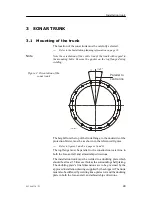
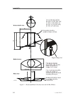
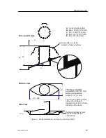
Страница 45: ...of the trunk flange to the underside of the protection blister must be as shown in the referenced figures Refer to figures 5 and 6 on pages 32 and 33 The top flange must be parallel to the constructio...

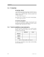
Страница 46: ...o figure 6 on page 33 Corrosion protection As soon as all installation welding and grinding has been performed the trunk and the surrounding area should be primed and painted using a quality protectiv...

Страница 47: ...Installation trunk 31 851 164336 D 3 4 Principles The drawings on the next pages illustrate the installation of the sonar trunk...

Страница 48: ...n bracket 1 4 6 mm The circular opening of the blister should have a diameter equal to the inside diameter of the trunk Deflection brackets should be welded only to the shell plating 3 4 knee plates m...

Страница 49: ...ister and deflection bracket 1 4 6 mm The circular opening of the blister should have a diameter equal to the inside diameter of the trunk Deflection brackets must only be welded to the shell plating...

Страница 50: ...ates the vessel hull it is very important that the hull unit is installed and secured properly This chapter describes the physical installation of the hull unit The following information is provided O...

Страница 51: ...as 1 2 m stroke length and it is designed for maximum speed 15 knots It will fit on a standard Simrad trunk with 540 mm pitch centre diameter PCD SP71 This hull unit has 1 2 m stroke length and it is...

Страница 52: ...esigned for maximum speed 20 knots It will fit on a standard Simrad trunk with 680 mm pitch centre diameter SP75 This hull unit has 1 0 m stroke length and it is designed for maximum speed 15 knots It...

Страница 53: ...eing manoeuvred into the sonar room CD6415B Upper limit switch Lower limit switch Transducer shaft Motor Control Unit Gantry Installation trunk Mounting flange Transducer Hoist Motor Figure 8 SP70 Hul...

Страница 54: ...t Observe the following procedure To ensure correct operation tick off every item when the action has been carried out 1 Use a tackle to lower the Hull Unit with the transducer protection in place int...

Страница 55: ...ransmission in air inside the trunk a pipe with a minimum inside diameter of 10 mm must be attached to the air bleeding cock This vent should be run with continuous rise to the main deck or through th...

Страница 56: ...chanical support of the hull unit gantry is satisfactory To prevent unwanted vortex induced vibration the Hull Unit must be secured to the bulkhead Use the two pre drilled holes on the gantry to mount...

Страница 57: ...ent Note that the transducer should not be mechanically aligned even though the Hull Unit is oriented differently than shown Transducer alignment will be later performed in the ProcessorUnit by rotati...

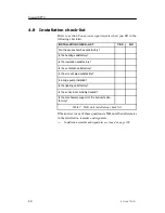
Страница 58: ...sulation satisfactory Is the ventilation satisfactory Is the air vent pipe satisfactory Is a bilge pump installed Is the lighting satisfactory Is the sonar room suitably decked Is the mechanical suppo...

Страница 59: ...rocedure Free bulkhead space is required to mount the Transceiver Unit cabinet Drawing references see pages 46 44 and 45 Procedure Observe the following procedure To ensure correct operation tick off...

Страница 60: ...SP70 44 851 164336 D Figure 11 Mounting the brackets for the Transceiver Unit side view Angle bars with threaded holes for shock absorbers Bars supplied by Simrad 680 2 680 5 Overhead Deck Bulkhead C...

Страница 61: ...Transceiver unit 45 851 164336 D Figure 12 Mounting the brackets for the Transceiver Unit forward view CD1988A App 40 150 Min 150 Min Recommended 1100 1200 Min 300 Min 75 150 Min 470 10 App 70...

Страница 62: ...Simrad SP70 46 851 164336 D Figure 13 Mounting the Transceiver Unit CD3110A...

Страница 63: ...Overview This chapter explains how to install the SP70 hardware units normally positioned in the wheelhouse Topics Location page 48 Colour display page 51 Operating Panel page 52 Sonar Processor Unit...

Страница 64: ...tallation requirements Installation of the wheelhouse units must be performed by qualified and trained personnel with regard to The safe navigation of the vessel The Compass safe distance for each ind...

Страница 65: ...wed for when planning the unit s location Standard compass 0 05 m Steering compass 0 05 m Sonar Processor Unit The Sonar Processor Unit MC70 should be installed inside a console in a cabinet or on a d...

Страница 66: ...udspeaker Choosing a location and installation of the loudspeaker should be done with regard to utility The compass safe distance must be allowed for when planning the unit s location Standard compass...

Страница 67: ...al equipment For installation and operation of the chosen display unit refer to the manual supplied with the unit Refer to page 6 for more information about the displays available from Simrad 1 Mount...

Страница 68: ...re four screws four nut plates and four bolt covers are supplied in the standard delivery 2 Drill and cut the panel opening as shown in the figure 3 Mount the Sonar Operating Panel using the supplied...

Страница 69: ...e following procedure To ensure correct operation tick off every item when the action has been carried out 1 Prepare the mounting location 2 Dismountthemounting framewith theshock absorbersfrom the So...

Страница 70: ...unit Provide enough space for easy access to the cabling 149 mm 7 mm 253 mm CD7026 Figure 17 Mounting the Sonar Interface Unit Observe the following procedure To ensure correct operation tick off ever...

Страница 71: ...ay unit Provide enough space for easy access to the cabling Observe the following procedure To ensure correct operation tick off every item when the action has been carried out 1 Prepare the mounting...

Страница 72: ...orresponding maritime authority and or classification society If no such guide lines exist Simrad AS recommends that Det Norske Veritas DNV Report No 80 P008 Guidelines for Installation and Proposal f...

Страница 73: ...cables are marked on the cable plan with an asterisk Cables provided by the shipyard performing the installation or the shipowner System cables Most system cables in the standard delivery are supplie...

Страница 74: ...rd A C9 Keyboard B C5 Serial C6 Cheapernet Cables identified with an asterisk are provided by Simrad C12 Course gyro C13 GPS Log C14 Echo sounder C24 Scientific data output C25 Synchronization Transce...

Страница 75: ...r Cable details on page 186 C2 Display This is a standard VGA or DVI display cable It is normally provided by the display manufacturer VGA Cable details on page 189 C4 C5 C6 Sonar Interface Unit This...

Страница 76: ...The transducer cables are provided by the manufacturer They are physically connected to the top of the transducer shaft All transducer cables are provided by Simrad C17 Motor control This cable is co...

Страница 77: ...onnectors are identified with Jx tags Note The Sonar Processor Unit provides a large number of connectors that are not used by the SP70 sonar Connections to the Sonar Interface Unit are made on the te...

Страница 78: ...nar Processor Unit and the Sonar Interface Unit Figure 19 Connections to the Sonar Processor Unit C3 AC mains C2 Video C7 USB C8 Serial C4 Control C6 Cheapernet C5 Serial CD717A C9 Operating Panel J4...

Страница 79: ...inated in the computer end with a male 15 pin Delta connector VGA or a special DVI connector The cable is normally supplied by the display manufacturer VGA Cable details on page 189 Observe the follow...

Страница 80: ...he cable length is 1 2 m 1 Connect the plug to the connector on the circuit board in slot J5 on the rear side of the Sonar Processor Unit Cable details on page 178 C6 Cheapernet communication This is...

Страница 81: ...able from the Operating Panel to the Sonar Processor Unit and the Sonar Interface Unit This dual cable has a common 15 pin Delta connector in the Operating Panel end a 9 pin female Delta connector in...

Страница 82: ...andard delivery with a length of 100 meters and it has a pre connected plug in the Sonar Interface Unit end Cable details on page 183 1 Run the 100 m data cable from the wheelhouse to the sonar room N...

Страница 83: ...ng all cables connected to the Transceiver Unit must have appropriate slack to allow for approximately 10 cm cabinet movement in all directions Cables C17 Motor control This cable is connected between...

Страница 84: ...ble from the Transceiver Unit to the Motor Control Unit mounted on the gantry 5 Use the cable gland on the right hand side in the Motor Control Unit and terminate the cable shielding in the cable glan...

Страница 85: ...the control and data cable from the Sonar Interface Unit in the wheelhouse to the Transceiver Unit in the sonar room The cable is included in the standard delivery with a length of 100 meters and has...

Страница 86: ...the referenced cable drawing The connections are made to the Motor Control Unit Refer to the detailed cable drawing on page 187 Observe the following procedure 1 Set the hoisting lowering switch S302...

Страница 87: ...the connector Figure 25 Power units in the Transceiver Unit ANALOG POWER SUPPLY SWITCHED POWER SUPPLY SERVICE OFF NORMAL ON OFF RELAY 24V STAND BY CAUTION DO NOT PULL OUT THIS UNIT BEFORE THE METER S...

Страница 88: ...sition 4 Connect the mains power cable to a normal mains outlet in the sonar room If the delivered cable connector does not fit use an adaptor or replace with a suitable plug For connection of the mai...

Страница 89: ...loop of cable having a length proportional to the possible expansion of the joint must be provided The minimum internal radius of the loop must be at least twelve times the external diameter of the c...

Страница 90: ...storage spaces and cargo spaces must be protected by a suitable casing or conduit even when armoured if the cable covering does not guarantee sufficient protection for the cables Metallic materials u...

Страница 91: ...tions are used for all cable conductors especially those that are to be connected to terminal blocks In this case crimped sleeve terminations must be fitted to prevent the conductor core from fraying...

Страница 92: ...t before mentioned in a later chapter Required inputs The SP70 sonar system requires input from both a speed log and a course gyro Inaccurate data from either of these instruments will result in an in...

Страница 93: ...and TB7 in the bottom row TB4 TB8 CD7014 TB1 through TB7 are all RS 232 serial line connections These may be used for any of the serial line auxiliary inputs Which input is used for which peripheral d...

Страница 94: ...output must be free from other connections The figure to the left shows the connection of a pulse log with relay output to terminal TB8 in the Sonar Interface Unit For connection of a pulse log with...

Страница 95: ...rse data Refer to the cable connection drawing for termination of the serial line data in the Sonar Interface Unit Refer to drawing on page 181 For connection to the speed log refer to the applicable...

Страница 96: ...erial line data in the Sonar Interface Unit Refer to the drawing on page 181 For connection to the course gyro refer to the applicable gyro documentation Gyro with 3 phase synchro or stepper output If...

Страница 97: ...peed log information Most D GPS systems are equipped to present the course information but this data is generally too inconsistent to provide a stable sonar presentation The sonar can read the D GPS d...

Страница 98: ...mat RS 232 serial line may be connected Most Simrad echo sounders have the depth output available on an RS 232 serial line Refer to the cable connection drawing for termination of the serial line data...

Страница 99: ...m in the vertical modes on the sonar When the ITI trawl system is connected to the SP70 sonar the information exchanged between the ITI and sonar is ITI to sonar Trawl position relative to vessel Dept...

Страница 100: ...ction To provide purse seine depth information on the sonar s display Simrad PI30 Purse seine system may be connected Refer to the cable connection drawing for termination of the serial line data in t...

Страница 101: ...ter systems Kaijo DCG 200 The interface is based on an RS 232 serial line Refer to the cable connection drawing for termination of the serial line data in the Sonar Interface Unit Refer to the drawing...

Страница 102: ...ERPE Ariane Ryokusei All these systems are interfaced by means of an RS 232 serial line Refer to the cable connection drawing for termination of the serial line data in the Sonar Interface Unit Refer...

Страница 103: ...tion to the standard operating panel an extra trackball or mouse with USB interface may be connected to the SP70 Sonar Processor Unit In such case all sonar operation may be controlled from this devic...

Страница 104: ...ry on The following procedures shall be performed Checklist before start up commences page 89 Staring the stand by power supply page 90 Staring up the Hull Unit page 92 Adjusting the middle position s...

Страница 105: ...the Sonar Interface Unit in the wheelhouse J3 connector for C15 CD7011 Figure 29 C15 connects to socket J3 in the Sonar Interface Unit Transceiver Unit 2 Check that the ship s mains fuses to the Trans...

Страница 106: ...ing procedure to start up the stand by power supply To ensure correct operation tick off every item when the action has been carried out 1 Check that the mains input connector P201 on the front of the...

Страница 107: ...age 115 Vac or 230 Vac position 6 Reinsert the mains input connector P201 on the front of the power supply 7 Check that lamps L201 and L202 on the front of the power supply illuminate 8 Check that the...

Страница 108: ...efore you start the functional check make sure that the mains fuses for the hull unit has been disconnected in the fuse box This check will only require the 24 Vdc standby power from the Transceiver U...

Страница 109: ...r to figure 32 on page 94 8 Remove the hand crank from the shaft but do not place it back into the Motor Control Unit 9 Set the hoisting lowering switch S302 to Hoist position and check that the hoist...

Страница 110: ...75 CD3421B Figure 32 Hand crank 12 Place the hand crank back into its storage position in the Motor Control Unit 13 Activate the hoisting contactor K301 by setting the hoisting lowering switch S302 t...

Страница 111: ...hase The hoist lower motor is normally pre wired for 380 440 Vac three phase If the measured three phase voltage is 230 Vac the motor must be rewired 1 Remove the 3 phasemains fusesfor thehull unitin...

Страница 112: ...hip s 3 phase mains fuses b Change two of the connections to the terminals on the motor overload switch S301 c Reinsert the 3 phase mains fuses in the ship s fusebox 6 Set the hoisting lowering switch...

Страница 113: ...the transducer Hoisting will be stopped automatically when the top of the transducer makes contact with the upper limit switch S304 12 Repeat the hoisting lowering operation to find the best position...

Страница 114: ...not possible to measure the distance X it can be calculated using the total trunk height D Use the table below to perform the calculation Total trunk height D mm Distance flange transducer bottom 760...

Страница 115: ...Start up procedures 99 851 164336 D 760 mm X D X 425 mm Magnet Middle position switch CD3422 Figure 34 Adjusting the middle position switch...

Страница 116: ...e serious damage to the system Start up Observe the following procedure for starting up the sonar 1 Connect the Sonar Processor Unit s AC mains plug 2 Press the Power button on the display unit Check...

Страница 117: ...Move the cursor to the Setup tab on the right hand side of the main menu and press the Select button The Setup menu will be displayed b Move the cursor to the Test button in the Setup menu and press...

Страница 118: ...View Object SONAR OPERATING PANEL TILT Manual Auto VARIOUS Zoom Record Off Centre Position Track Manual Target Track Auto Search TRAIN CD5377A WMF GIF SIMRAD 1 2 3 4 5 8 9 6 7 Functional test Observe...

Страница 119: ...Check the Circle Marker a Press the Circle Marker button field 2 third button b Check if a circle appears centred around the cursor c Press the button once more and check that the circle marker disapp...

Страница 120: ...peatedly field 4 on the Operating Panel c Check that the Gain readout in vertical the menu can be changed from 0 to 50 10 Check the Vertical range readout a Press the Range V and Range V buttons repea...

Страница 121: ...Auto button e Check that the tilt limits appear on the Tilt indicator f Press Manual to stop the automatic tilt program Zoom view 15 Check the Zoom function a Select Mode 1 Bow Up b Move the cursor to...

Страница 122: ...et circle disappears 21 Check the Auto search function a Press the Auto Search button field 9 b Check that the audio line starts a search within the displayed sector limits c Press the Manual button t...

Страница 123: ...in the sonar room must press the red button marked 0 on the motor overload switch S301 in the Motor Control Unit Refer to figure 31 on page 93 The following two procedures must be performed simultanou...

Страница 124: ...oom to perform the next step 3 Sonar room Press the black button marked 1 on the motor overload switch S301 in the Motor Control Unit 4 Sonar room Set the hoist lower switch S302 in the Motor Control...

Страница 125: ...position b Check that the LED next to the Up button starts to flash and that the audible signal indicates transducer movement c When upper position has been reached check that the LED next to the Up b...

Страница 126: ...d Notify the sonar room to perform the next step 11 Sonar room Set the hoisting lowering switch S302 in the Motor Control unit to the Stop position 12 Switch off the sonar a Press the Power button on...

Страница 127: ...rt up procedures 111 851 164336 D Blank page This page is intentionally left blank It allows you to remove the next test procedure from the manual and bring it down to the sonar room during the proced...

Страница 128: ...on marked 1 on the motor overload switch S301 in the Motor Control Unit 4 Set the hoist lower switch S302 in the Motor Control Unit to Remote a Notify the bridge to perform the next step 5 Bridge Lowe...

Страница 129: ...0 112751 POWER SUPPLY 290 112750 100 50 0 1 5 0 Service switch S202 Fuses F204 F205 Lamp L205 Lamp L201 Lamp L202 Lamp L203 Lamp L204 CD3118C GIF Figure 38 The lamps fuses and service switch on the po...

Страница 130: ...r approximately two seconds 8 Checkthatthe TransceiverUnit startsup afterapproximately two minutes and the two LEDs marked COM on the top of the SPB 31 circuit board starts to flash The COM and TXEN L...

Страница 131: ...u in the lower part of the menu field d Select Noise VR to select the Noise test menu settings After the preparations described above has been carried out the echo level for the selected audio beam wi...

Страница 132: ...amage to the transducer and the transmitters Preparations In order to prepare the system start up carry out the following operations in the Transceiver Unit and the motor control unit 1 Connect and fa...

Страница 133: ...eiver Unit works properly Make sure that proper communication exists between the two locations Note Should problems occur in the sonar room the person in the sonar room must set the service switch S20...

Страница 134: ...V Powerunit shows approximately 25 V 6 Sonar room Check that the TX Enable LED TXEN on the TIB board starts flashing For location of the TXEN LED refer to figure 39 on page 117 7 Set the TX Power in t...

Страница 135: ...rt up procedures 119 851 164336 D Blank page This page is intentionally left blank It allows you to remove the next test procedure from the manual and bring it down to the sonar room during the proced...

Страница 136: ...r in the Horizontal menu to Low and check that echoes appear on the display 5 Check that the voltmeter on the HV Power unit shows approximately 25 V 6 Check that the TX Enable LED TXEN on the TIB boar...

Страница 137: ...is installed different from the recommended orientation previously described you must carry out this procedure to align the sonar echo on the display Therecommended orientation is shown in section Hul...

Страница 138: ...ocedure To align the sonar picture Observe the following procedure to align the sonar picture 1 Locate the 0 degrees transducer mark 2 Estimate the approximate alignment angle 0to 360degrees clockwise...

Страница 139: ...menu field f Press the Alignment button g Enter the estimated alignment angle 4 Check that the echo picture on the display is correct in relation to the ambient situation If not make a fine adjustment...

Страница 140: ...lled to established the type 2 Use the information in the two next sections to define the alignment angle 3 Carry out the common procedure below to align the sonar picture SP70 Hull Unit On the standa...

Страница 141: ...or is always related to the gantry as indicated in the figure below BOW CD6348 0 transducer mark O 0 stabilisation sensor O Offset angle Figure 42 Offset angle definition Observe the following procedu...

Страница 142: ...a parameter into the sonar system 1 Select the Setup menu 2 Press the Test to bring up the System test menu 3 Press the Installation Menu button and observe the menu appears on the top of the display...

Страница 143: ...a new display mode is selected the vessel symbol will change to the selected size Instrument position offsets In order to get correct references of the instruments the position of the sonar transduce...

Страница 144: ...nish 7 Select Own Ship on the Installation menu then Instrument Position Offsets and finally GPS 8 Observe the Instrument Offset Positions menu appear at the bottom of the menu field 9 Press the X Pos...

Страница 145: ...ystem shall be set up to accept the signals from the sensors The following information is provided General information page 130 Speed log page 133 Course gyro page 135 D GPS page 137 Echo sounder page...

Страница 146: ...Press the Test button to open the System Test menu 3 Press the Installation Menu button 4 Observe the Installation menu appear on the top of the display 5 Select I O Setup on the Installation menu an...

Страница 147: ...ing the telegram format of the received data Use the following procedure for viewing of the Object Inspector 1 Select the Setup menu 2 Presse Test button to open the System test menu 3 Press the Messa...

Страница 148: ...me way 8 Observe the list of communication ports 9 Press the sign in front of the actual serial port 10 Press the COM symbol under the serial port The Object Inspector will display the transmit and re...

Страница 149: ...s in the Sensor Config menu correspond to the sensor settings table Note that the pulse log must use serial port no 9 4 Press Close to exit the Sensor Config menu 5 Check that the speed readout in the...

Страница 150: ...s to the I O Setup page 130 Speed data from D GPS If the GPS is used for the speed data input wait with this test until the GPS position data are tested Observe the following procedure to test the GPS...

Страница 151: ...bserve the following procedure to test the course gyro input 1 Access the I O Setup menu 2 Select Sensors in the I O Setup menu then Heading and finally Gyro 3 Observe the Sensor Config submenu appear...

Страница 152: ...of the menu field 4 Change the settings in the Sensor Config submenu to suit your requirements for the serial line 5 Press Close to exit the Sensor Config menu 6 Check that the heading readout in the...

Страница 153: ...0 2 Select Sensors in the I O Setup menu then Pos System and finally GPS 3 Observe the Sensor Config submenu appears at the bottom of the menu field 4 Check that the settings in the Sensor Config subm...

Страница 154: ...for this is located on page 130 2 Select Sensors in the I O Setup menu then Echo sounder and finally EchoNmea 3 Observe the Sensor Config submenu appears at the bottom of the menu field 4 Check that t...

Страница 155: ...or Config submenu appears at the bottom of the menu field 4 Check that the settings in the Sensor Config submenu correspond to your requirements for the serial line 5 Press Close to exit the Sensor Co...

Страница 156: ...fig submenu appears at the bottom of the menu field 4 Check that the settings in the Sensor Config submenu correspond to your requirements for the serial line 5 Press Close to exit the Sensor Config m...

Страница 157: ...nu then BuoySystem and finally Buoy NMEA 3 Observe the Sensor Config submenu appears at the bottom of the menu field 4 Check that the settings in the Sensor Config submenu correspond to your requireme...

Страница 158: ...Current meter and finally Kaijo 3 Observe the Sensor Config submenu appears at the bottom of the menu field 4 Check that the settings in the Sensor Config submenu correspond to your requirements for...

Страница 159: ...erify that the sonar works properly the following measurements and tests must be carried out Source Level SL measurements page 144 Receiving voltage response VR page 148 Noise speed curve page 151 To...

Страница 160: ...y you need to hook up the test equipement Refer to figure 46 for the necessary test schematics Preparing the operational mode For measurement of the source level in omni mode use the following menu se...

Страница 161: ...ydrophone and adjust the tilt on the sonar to get maximum voltage on the oscilloscope at a tilt angle of 0 degrees 5 Measure the time delay from the negative going TX Enable pulse to the transmitter p...

Страница 162: ...ble The Measurement results table is shown as table 4 15 Enter the 20 log r and U Hydr values from the Measurements results table into the Source Level SL table The Source Level SL table is shown as t...

Страница 163: ...able into the Source Level SL table The Test Hydrophone Data table is shown as table 3 on page 144 17 Perform the SL calculations as detailed in the table and compare the result with the specification...

Страница 164: ...following procedure to measure the receiving voltage response Note that the procedure calls for an oscilloscope and a test oscillator 1 Check that the bearing and tilt angle values are the same as fo...

Страница 165: ...le 7 10 Retrieve the Hydrophonesensitivity astransmitter Sfrom the Test hydrophone data table The Test hydrophone data table is shown as table 3 on page 144 Source level measurements 11 Enter the data...

Страница 166: ...Simrad SP70 150 851 164336 D Measurement termination The voltage response measurements have now been completed Remember to restore all menu settings to normal operational standard...

Страница 167: ...o level button in the System test menu provides a readout of the current value measured by the sonar Procedure Observe the following procedure to make the noise speed curve 1 Start with 0 knots with t...

Страница 168: ...down Thislower gainwill then cause a reduction in the receiving range To find out if this high noise level is caused by flow noise from the vessel s hull or by the engine propeller perform the followi...

Страница 169: ...se into the Noise speed plot and a dotted line for the retardation noise By comparing these three plots it should be possible to sort out if the main noise is caused by flow noise or engine propeller...

Страница 170: ...NOISE SPEED CURVE FOR 0 BEARING WITH dB 6 MAXIMUM GAIN dB 4 _________STABLE SPEED ACCELERATION RETARDATION dB 2 RETARDATION dB 0 dB 2 dB 4 dB 6 dB 8 dB 10 dB 12 dB 14 dB 16 dB 18 dB 20 dB 0 2 4 6 8 10...

Страница 171: ...nal voltage Transient 20 of nominal voltage recover time 3 s Power consumption 600 VA Frequency 47 to 63 Hz Hull Unit Voltage Nominal 230 380 440 Vac 3 phase selectable Deviation 230 Vac 15 of nominal...

Страница 172: ...ximately 75 kg Dimensions WDH 520 x 505 x 750 mm including shock absorbers Refer to the Transceiver Unit outline dimensions drawing on page 195 Display Unit Refer to the documentation for the applicab...

Страница 173: ...face Unit Operational temperature 0 to 40 C Storage temperature 40 to 70 C Humidity 5 to 95 relative non condensing Transceiver Unit Operational temperature 0 to 40 C Storage temperature 40 to 70 C Hu...

Страница 174: ...il in this chapter The table below provides an overview of the different telegrams received from the peripherals Gyro Speed log GPS ITI FS 900 HDM HDT VBW VTG GLL GGA VTG ZDA IITPT IITPC IIGLL IIDBS I...

Страница 175: ...used for receiving and transmitting sensor data The following approved sentence structure are used for all NMEA data aaccc c c hh CR LF For some telegrams received from other Simrad equipment the cha...

Страница 176: ...Heading magnetic HDM x x M cr lf where from left towards right Component Content Talker HDM identifier code for the type of system used x x heading in degrees magnetic Heading true HDT x x M cr lf whe...

Страница 177: ...right Component Content Talker VBW Identifier code for the type of system used mm mm longitude water speed indication sign or nn nn transverse water speed don t care T A or V water_track status A data...

Страница 178: ...ne using the NMEA 0183 standard for reception of clock information The SP70 will receive the following NMEA telegram Time and date Time and date ZDA hhmmss ss dd MM yyyy xx xx hh cr lf where from left...

Страница 179: ...legram router ITI Inputs The SP70 can receive the following trawl telegrams from the ITI system Trawl position true vessel Trawl position in cartesian co ordinates Trawl position in latitude and longi...

Страница 180: ...s right Component Content GLL The trawl s geographical latitude and longitude ddmm hh N Latitude in degrees minutes and hundredths N North S South dddmm hh W Longitude in degrees minutes and hundredth...

Страница 181: ...bottom Trawl door spread IITDS x x M cr lf where from left towards right Component Content TDS Trawl door spread distance x x M Distance in meters Trawl Spread 2 IITS2 x x M cr lf where from left towa...

Страница 182: ...tal distance from the trawl to the shoal the direction of the vessel s centre line z M Vertical distance from the trawl to the shoal Heading magnetic HDM x x M cr lf where from left towards right Comp...

Страница 183: ...target relative to the vessel head ing resolution is 1 degree zzzz M Target s depth below the surface resolution is 1 meter nn Target identification 00 Echo target currently tracked 10 Position curre...

Страница 184: ...S3300 system sends a 2 byte binary depth value With a measurement in units of 0 1525879 m the data format is Osbbbbbb bbbbbbbb where from left towards right Component Content O Indicates valid output...

Страница 185: ...eographical position GLLddmm hh N dddmm hh W hhmmss ss A cr lf where from left towards right Component Content Code for the system used OM Omega LC Loran C etc GLL Geographical latitude longitude ddmm...

Страница 186: ...n dredths N North S South ddmm hh W Longitude position in degrees minutes and hun dredths W West E East x Quality factor xx Number of satellites in use x x Horizontal dilution x x Mean sea level M Met...

Страница 187: ...where from left towards right Component Content SD Talker DBS Depth of water below surface x x f Depth in feet y y M Depth in meters z z F Depth in fathoms Sounder depth below transducer DBT x x f y y...

Страница 188: ...Sounder depth below surface Special This telegram has been developed by Simrad SDDBS y y M tttttt cr lf where from left towards right Component Content SD Talker DBS Depth of water below surface y y D...

Страница 189: ...ade via Ethernet or on a serial line Standard NMEA 0183 formats are used on the serial line The SP70 receives the following NMEA telegrams Water propagation speed Water propagation speed YWP x x f x x...

Страница 190: ...Wind speed and angle relative Wind direction and speed MWD x x T x x M x x M cr lf where from left towards right Component Content Talker MWD Wind direction and speed x x T Wind direction true x x M W...

Страница 191: ...4336 D Wind speed and angle relative VWR x x a x x a A cr lf where from left towards right Component Content Talker VWR Wind speed and angle x x Wind angle x x Wind speed knots N Knots xx Wind speed m...

Страница 192: ...page 181 C15 W208d Control signals to transceiver page 183 C16 Transducer cable C17 W234 Hull Unit control page 185 C18 W301 AC power page 186 C19 W312 AC power to hull unit page 187 C20 W208b Serial...

Страница 193: ...SP72 Sonar Mounting Trunk refer to page 201 SP73 SP74 Sonar Mounting Trunk refer to page 202 Optional trunk outline dimensions SP70 SP75 Optional trunk outline dimensions page 203 SP71 SP72 Optional t...

Страница 194: ...nterface Unit C4 Control C5 Serial W206A Rev A Control and Serial cables Cable C4 Connects to the far right hand connector on the rear side of the Sonar Processor Unit Cable C5 Connects to circuit boa...

Страница 195: ...y1 5 m Note that one end of the cable is equipped with a T connection This end of the cable must be connected to the Sonar Processing Unit W206B Rev A Cheapernet cable This end connects to J7 in the S...

Страница 196: ...nterface Unit Loudspeaker The loudspeaker cable is physically connected to the loudspeaker unit and as such a part of the delivery W208A Rev B Loudspeaker 6 2 1 8 11 4 7 10 3 9 12 5 Sonar Interface Un...

Страница 197: ...e Sonar Interface Unit 2 1 4 3 5 Sonar Interface Unit TB1 7 RX RX TX TX GND The Sonar Interface Unit is equipped with seven serial line communication ports TB1 COM2 TB3 COM4 TB5 COM6 TB7 COM8 TB2 COM3...

Страница 198: ...v A Pulse log 6 2 1 8 11 4 7 10 3 9 12 5 Sonar Interface Unit TB8 Speed log Speed log Ground Pulse log with relay output These cables are not included with the delivery and must be provided by the ins...

Страница 199: ...8D Rev A Sonar Interface Unit Transceiver Unit 1 31 47 35 1 1 2 2 3 3 4 4 5 5 6 6 7 7 8 8 15 27 43 2 29 45 16 25 41 4 23 39 18 19 35 5 21 37 19 17 33 7 15 21 11 8 13 22 9 10 7 11 5 24 3 25 1 1R 24 Vdc...

Страница 200: ...lows external synchronization of the sonar s transmission W208F Rev A Synchronization 6 2 1 8 11 4 7 10 3 9 12 5 Sonar Interface Unit TB8 TX Sync Sync IN Sync OUT Ground Conductors 4 x 0 5 mm2 Screen...

Страница 201: ...l Unit 1 32 54 3 28 2 30 4 26 42 5 24 40 7 20 36 6 22 38 8 18 34 9 16 11 12 10 14 12 10 13 8 14 6 15 4 2 1R 1R 1BL 2R 2BL 1BL 3R 3BL 4R 4BL 5BL 6BL 7BL 5R 6R 7R 2R 2BL 3R 3BL 4R 4BL 5R 5BL 6R 6BL 7R 7...

Страница 202: ...er end is terminated in a plug suitable for the local standard W301 Rev B Standard power cable for 115 230 Vac 2 phase Live normally Blue Neutral normally Brown Use the applicable plug to suit local s...

Страница 203: ...the motor connections to match the power available W312 Revision B AC 3 phase power to Hull Unit 230 380 440 Vac 3 phase mains Fused 10A slow S301 in the Motor Control Unit 380 440 Vac 230 Vac Motor c...

Страница 204: ...g Ethernet 10Base T Straight Through Ethernet 10Base T Crossover The crossover cable is used to cascade HUBs or for connecting two ethernet stations or computers back to back without a HUB NOTE In ord...

Страница 205: ...normally physically fastened to the display unit and it is provided with the plug s readily attached W500 Rev A Standard VGA cable 1 3 2 4 5 6 8 7 9 10 11 13 12 14 15 Red Ground NC Green Ground NC Blu...

Страница 206: ...ost kind of external devices The order number provided is for a 4 5 m cable W501 Rev A Commercial USB cable Universal Serial Bus USB cable terminated with an in one end and a in the other Internal cab...

Страница 207: ...d by the manufacturer W625 Rev B Order number 380 202101 860 202102 682 58 Operator panel P2 2 R P3 5 WH P3 2 R P2 5 WH P2 3 BL P3 1 GN P3 8 BL P3 7 BK P3 6 YE P4 1 BL P4 3 WH P4 2 R Pin 1 Pin 1 Pin 1...

Страница 208: ...The drawing is not in scale 385 115 MAIN SW SYMBOL TILT VARIOUS MODE SONAR OPERATING PANEL 91 165 Mode 4 Mode 1 Down POWER Mode 2 Up Mode 3 Middle GAIN Gain H Gain V Gain H Gain V Range H Range V Ran...

Страница 209: ...Drawing file 193 851 164336 D 410 375 202 441 452 267 N A Rev A Page 1 of 1 CD7006A MC70 Sonar Processing Unit Outline dimensions Note All measurements are in mm The drawing is not in scale...

Страница 210: ...64336 D 149 313 7 mm 253 280 CD7026B N A Rev A Page 1 of 1 CD7026B Sonar Interface Unit Outline dimensions Note All measurements are in mm The drawing is not in scale Allow access space underneath the...

Страница 211: ...t Transducer cable plug fastened with eight bolts Extender through insulation not supplied by Simrad Allow enough space for tools to mount the transducer cable plug All measurements are in mm Note tha...

Страница 212: ...Simrad SP70 196 851 164336 D 110 47 110 TBD Rev A Page 1 of 1 CD6366B Standard loudspeaker Outline dimensions All measurements in mm...

Страница 213: ...Drawing file 197 851 164336 D 275 11 2080 81 7 8 757 29 3 4 990 39 1200 47 1 4 Dia 580 22 7 16 Dia 508 20 432 17 xxx xxxxxx Rev A Page 1 of 1 CD5861 SP70 The Hull Unit outline...

Страница 214: ...5 mm 17 5 SP71 SP72 SP73 SP74 676 mm 26 6 761 mm 30 810 mm 31 9 SP71 SP72 SP73 SP74 546 mm 21 5 610 mm 24 382 mm 15 SP71 SP73 SP72 SP74 1200 mm 47 2 1600 mm 63 N A Rev A Page 1 of 1 CD6529 SP71 SP72 S...

Страница 215: ...199 851 164336 D 375 mm 14 8 580 mm 22 8 1000 mm 39 4 508 mm 20 990 mm 39 755 mm 29 7 1645 mm 64 8 N A Rev A Page 1 of 1 CD6923 SP75 Hull Unit Outline dimensions All measurements in mm The drawing is...

Страница 216: ...22 5O Classification society marking 540 460 1 0 580 2 508 Standard 990 3 Minimum 810 3 12 5 45 10 18 0 1 22 5 830 113361 Rev A Page 1 of 1 CD5859B SP70 and SP75 Mounting trunk Outline dimensions All...

Страница 217: ...arge no 20 HOLES M24 Classification society marking 25 25 670 2 506 810 5 520 1 1 6 871 205555 Rev B Page 1 of 1 CD6945 SP71 SP72 Sonar mounting trunk Note All measurements are in mm The drawing is no...

Страница 218: ...nting trunk Note All measurements are in mm The drawing is not in scale 760 2 5 0 2 0 34 1 0 614 0 1 576 1 561 1 0 810 5 Classification society marking Section A A Charge no 570 610 25 25 25 0 4 A 2 A...

Страница 219: ...Drawing file 203 851 164336 D 580 508 990 N A Rev A Page 1 of 1 CD5860 SP70 SP75 Optional trunk outline dimensions Note All measurements are in mm The drawing is not in scale...

Страница 220: ...Simrad SP70 204 851 164336 D N A Rev A Page 1 of 1 CD6943 SP71 SP72 Optional trunk outline dimensions 670 546 Note All measurements are in mm The drawing is not in scale 810...

Страница 221: ...Drawing file 205 851 164336 D N A Rev A Page 1 of 1 CD6948 SP73 SP74 Optional trunk outline dimensions Note All measurements are in mm The drawing is not in scale 760 610 810...

Страница 222: ...SP70 206 851 164336 D 830 113362 Rev A Page 1 of 1 CD5846 SP70 SP75 Blind cover for sonar trunk 540 580 2 18 0 5 0 5 16 holes spacing 22 5o 13 2 0 Note All measurements are in mm The drawing is not in...

Страница 223: ...205559 Rev B Page 1 of 1 CD6328B SP71 SP72 Blind cover for sonar trunk 480 2 18 1 0 0 25 1 6 25 1 2 5 20 HOLES 18 9 2 M10 x2 670 2 620 27 2 2 DRILLING DEPTH min 5mm 60 0 2 100 5 Note All measurements...

Страница 224: ...4 Blind cover for sonar trunk 1 6 25 6 3 R1 0 25 5 5 0 2 760 0 2 555 1 620 0 1 28 1 0 27 1 0 A A Section A A 1 1 24 holes 760 680 Drilling depth max 6 mm 2 2 x2 First priming only in the groove 60 0 2...

Страница 225: ...S Use these pages to document comments and remarks concerning the installation When the installation has been fully completed and all functional tests have been perfomed to full satisfaction represent...

Страница 226: ...Simrad SP70 210 851 164336 D Party Date Signature Party Date Signature Party Date Signature...

Страница 227: ......

Страница 228: ...2003 Simrad AS ISBN 82 8066 010 0 Simrad AS Strandpromenaden 50 Box 111 N 3191 Horten Telephone 47 33 03 40 00 Facsimile 47 33 04 29 87 A L W A Y S A T T H E F O R E F R O N T O F T E C H N O L O G Y...

Страница 229: ......
Страница 230: ...Simrad SP70 Installation manual Simrad SP70 Installation manual Simrad SP70 Installation manual Simrad SP70 Installation manual...

Отзывы:

Похожие инструкции для Simrad SP70