Document number: 13798E
Version: 3
Valid from: S/N 283010 / SW 129
INSTRUCTION MANUAL
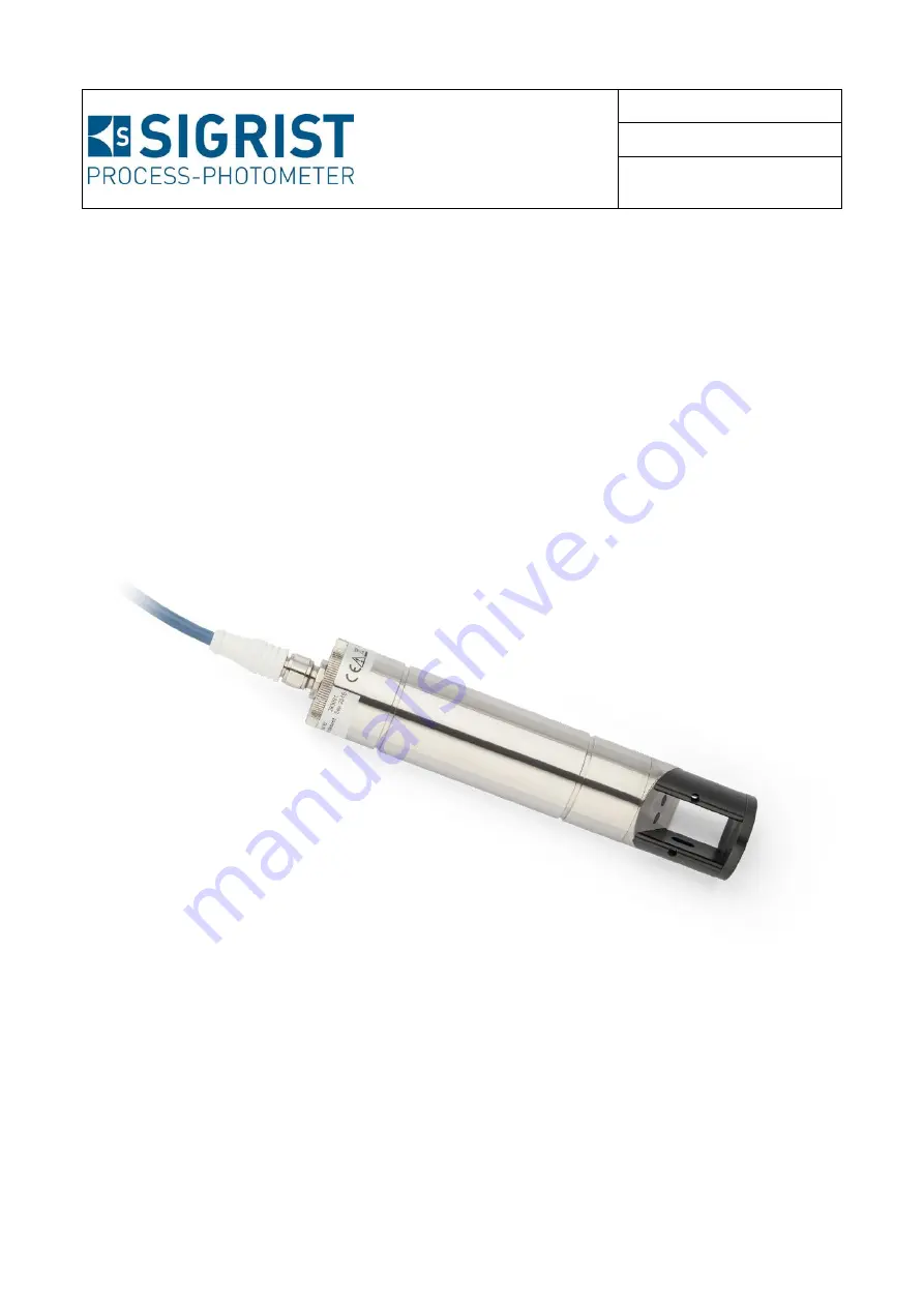
AquaScat S
Turbidity probe for water treatment
Страница 1: ...Document number 13798E Version 3 Valid from S N 283010 SW 129 INSTRUCTION MANUAL AquaScat S Turbidity probe for water treatment...
Страница 2: ...T PHOTOMETER AG subject to technical changes without notice 2 2019 SIGRIST PHOTOMETER AG Hofurlistrasse 1 CH 6373 Ennetb rgen Switzerland Tel 41 41 624 54 54 Fax 41 41 624 54 55 info photometer com ww...
Страница 3: ...afety points 21 3 1 Dangers when properly used 21 3 2 Residual risk 22 3 3 Warning and danger symbols on the instrument 22 3 4 Preventing undesirable online access attempts 23 4 Mounting 24 4 1 Basic...
Страница 4: ...0 7 Operation 52 7 1 Operation basics 52 7 2 LED display in the Conn R junction box 53 7 3 Control elements in measuring operation 54 7 4 Menu button 54 7 5 Valu button 54 7 6 Info button 55 7 6 1 Pag...
Страница 5: ...calibration with the Conn R junction box 88 9 6 3 Recalibration with SICON 90 9 6 4 Recalibration without SICON 92 9 7 Changing the battery in the SICON 94 10 Troubleshooting 95 10 1 Pinpointing malfu...
Страница 6: ...Instruction Manual AquaScat S Contents 6 13798E 3 This page is intentionally blank Makro...
Страница 7: ...strument 1 4 Additional documentation DOC NO TITLE CONTENT 13799E Brief Instructions The most important functions and the servicing schedule 13800E Reference Manual More sophisticated menu functions a...
Страница 8: ...uction Manual 1 10 Declaration of conformity Current technological principles were followed in designing and manufacturing the instru ment They comply with the applicable guidelines concerning safety...
Страница 9: ...per changes to the instrument have been performed The instrument has not been operated within the specifications in particular concerning pressure and temperature The instrument is exposed to vibratio...
Страница 10: ...ing of the pictograms All pictograms used in this document are explained below Additional information about the current topic Practical procedures when working with the AquaScat S Manipulations on the...
Страница 11: ...nstrument overview 2 1 Overview of a measuring point Figure 1 Overview of a measuring point AquaScat S turbidity probe including 10 m cable Conn R junction box optional SICON C portable control unit o...
Страница 12: ...S The photometer is fitted with the following rating plate Figure 2 Rating plate on AquaScat S CE mark Observe the Instruction Manual Observe the disposal informa tion Manufacturer Product name Count...
Страница 13: ...box The Conn R junction box is fitted with the following rating plate Figure 3 Rating plate on Conn R junction box Manufacturer Country of origin Product name Serial number Date of manufacture 24 VDC...
Страница 14: ...C The SICON C portable control unit is fitted with the following rating plate Figure 4 Rating plate on SICON C Manufacturer Country of origin Product name Serial number Date of manufacture Service vo...
Страница 15: ...with connector Documents PCS DOC NO NAME VIEW VARIANT 1 13798 Instruction Manual German French English 1 13800 Reference Manual German English 1 13799 Brief Instructions German French English 2 3 2 Op...
Страница 16: ...r faces print For SICON M only 1 118445 Modbus RTU inter faces print For SICON M only 1 121121 Profinet IO inter faces print For SICON M only 1 119796 HART module For SICON M only 1 119130 4 way curre...
Страница 17: ...E VIEW VARIANT 1 120561 PE fitting 1 120562 Pipe flange 1 120563 Submerge tube 1 m standard equipment 120564 Submerge tube extension 1 m 1 120579 VARINLINE adap ter 1 120570 Extractable as sembly 1 Su...
Страница 18: ...FNU 0 002 FNU or 1 10 4000 FNU 2 Repeatability 0 001 FNU or 0 1 Service voltage 24 VDC 10 Power consumption 2 W Outputs 1 x current output 0 4 20 mA maximum burden 600 minus pole to ground on service...
Страница 19: ...ICON C Ethernet microSD card for logging SW update diagnostics Modbus TCP Optional Modbus RTU Profibus DP Profinet IO or HART Cur rent output 4 way module and Current input 4 way module Protection cla...
Страница 20: ...3798E 3 Conn R junction box Values Service voltage 24 VDC 10 Power consumption 0 5 W photometer Outputs 2 x relay outputs 230 VAC 4 A 1 x current output from photometer Protection class IP66 Weight 0...
Страница 21: ...s Improper manipulations on a pressurized pipe can lead to the sample escaping under pres sure resulting in injuries damage to the instrument and material damage on site Always consult the Instruction...
Страница 22: ...chemicals clean it thoroughly with a neutral cleaning agent 3 2 Residual risk WARNING According to the risk assessment of the applied safety directive DIN EN 61010 1 there remains the risk of the dis...
Страница 23: ...hen any Internet us er can in principle access your instrument and change the configuration Please note the following points to prevent this Never connect the instrument directly to the Internet Opera...
Страница 24: ...dpipe pos 1 The photometer can also be installed in pipes that run horizontally pos 3 Do not mount the photometer in the downpipe pos 2 The photometer must be mounted in the line at least 0 5 meters a...
Страница 25: ...e according to the AquaScat_S_PE MB dimensional drawing Figure 6 Overview of a measuring point with connection via PE fitting Absorber Pipe T piece for connection to sample line provided by the custom...
Страница 26: ...quaScat_S_RF MB dimension al drawing Figure 7 Overview of a measuring point with connection via pipe flange Absorber T piece with pipe flange DN 40 PN 40 provided by the customer for fastening the Aqu...
Страница 27: ...pling and posi tioned so that the handle of the shut off valve pos 3 is at the top The probe can then be reinstalled as detailed in Section 9 5 step 10 to 17 Insert the outlet hose pos X in the hose c...
Страница 28: ...according to the current installation situation The following three markings are found on the handle A Vertical line flow from below B Horizontal line flow from right C Horizontal line flow from left...
Страница 29: ...attach these to the submerge tube 2 Feed the connection cable through the sub merge tube 3 Connect the cable to the AquaScat S and firm ly tighten the screw connection 4 Insert the AquaScat S in the s...
Страница 30: ...e finally positioned against the flow direction of the sample so that the measuring cell can be well ventilated and no turbulence can build up The supplied pipe clamp pos 4 can be used to fasten the s...
Страница 31: ...dimensional drawing Figure 10 Overview of a VARINLINE measuring point Absorber VARINLINE adapter AquaScat S Marking on the rating plate shows the position of the angled edge pos 8 M12 connector femal...
Страница 32: ...AquaScat S must be protected against exposure to light The water to be measured must be free from air bubbles There must be no turbulence in the water in the immediate vicinity of the immersion probe...
Страница 33: ...ONAL INFO IMAGES 1 Open both flaps at the same time When both flaps are open the cover is not fixed in place and can fall out 2 Remove the cover from the housing on the Conn R junction box 3 Fasten th...
Страница 34: ...truction Manual AquaScat S Mounting 34 13798E 3 4 9 Mounting the SICON M WORKSTEP ADDITIONAL INFO IMAGES 1 Open the shutters 2 Fasten the control unit to the wall using four M4 x 10 hexagon socket scr...
Страница 35: ...nection device switch plug should be installed near the service voltage It must be designated and easily accessible The system must not be charged with voltage until the installation is completed and...
Страница 36: ...ibed on the Sec tion 7 2 Pin headers J1 4 fitted with jumpers To connect an AquaScat S jumpers must be fitted to the two right hand pins on the pin headers J1 J4 Terminal strip for relay outputs Termi...
Страница 37: ...Conn R junction box Description Connector pin male AQ S Wire color for device cable art no 120444 Conn R Remarks Supply GND 1 white 1 24 VDC power supply 2 brown 2 24 V 10 RS 485 A 7 blue 3 Serial in...
Страница 38: ...ed to earth through the installation then this connection can be left open 24 V power supply 11 24 V 12 GND 24 V 10 RS 485 13 A 14 B Not used Current output 15 16 The minus pole is connected to GND Ma...
Страница 39: ...with SICON M 5 3 1 Removing the cover from the SICON M WORKSTEP ADDITIONAL INFO IMAGES 1 Open the shutters 2 Loosen the fastening screws on the cover 3 Open the cover 4 Fasten the cover with the cover...
Страница 40: ...unit Figure 14 Overview of SICON Standard Park position for cover clamp microSD card card for log data USB connection Ethernet connection SD card adapter with holder Cover clamp in holding position Ba...
Страница 41: ...wing sequence must be adhered to TERMINAL MEANING REMARKS 1 8 11 Connection to the photome ter Insulate all unused cable ends Terminal 8 GND ground white Terminal 9 24V brown Terminal 10 A blue Termin...
Страница 42: ...parts may also be dam aged Local regulations for electrical installations must be observed at all times Figure 16 Terminals for submerge version with special cable on SICON Open the SICON according to...
Страница 43: ...andbook 5 4 1 Overview of Modbus RTU and Profibus DP Figure 17 Overview of field bus interfaces Field bus interface connection printed circuit board for Profibus DP Field bus interface connection prin...
Страница 44: ...integrated in the SICON M The module has an internal switch and provides two Ethernet ports The cable is connected directly to the RJ45 plug of the Profinet IO module inside the in strument or via ext...
Страница 45: ...RT Serves as interface to HART HART terminals 5 4 5 Connecting to HART The terminals of the HART module are configured as follows Terminals HART Functional description 1 mA In Must be connected with t...
Страница 46: ...20 Overview of the 4 way current output module 4 way current output Terminals 5 5 2 Connecting the 4 way current output The terminals of the 4 way current output are configured as follows Terminals 4...
Страница 47: ...g the 4 way current input The terminals of the 4 way current input are configured as follows Terminals 4 way current input Functional description 1 In 1 Current input 1 2 In 1 3 In 2 Current input 2 4...
Страница 48: ...ed and connected Section 4 and Section 5 2 2 1 Establish the service voltage to the Conn R junction box and thus to the photometer 2 2 Plug the SICON C into the Conn R junc tion box according to Secti...
Страница 49: ...tial start up is English 2 2 The instrument carries out an internal functional check 2 3 The instrument is ready for measurement 3 Set the language Section 8 1 4 Set the current outputs Section 8 2 5...
Страница 50: ...nnect the USB cable to the AquaScat arrow and connect to the PC The AquaScat S is automatically detected as a removable disk Windows operating system 3 3 Depending on the Windows configuration either...
Страница 51: ...1 Yes Invert Inverts output 1 alarm Output 2 Invert 0 No 1 Yes Invert Inverts output 2 limit Factory set 0 No 1 Yes Yes loads the factory setting 4 3 Close the file after making your entries Changes...
Страница 52: ...rence Manual The instrument has a touchscreen It is operated by touching with your finger The navi gation elements change color when touched CAUTION Sensitive touchscreen The touch screen can be damag...
Страница 53: ...ometer Meaning Measure LED permanently off Instrument is switched off or de fective Switch on the instrument LED flashes every 15 se conds The instrument is in measuring opera tion without faults LED...
Страница 54: ...screen Section 7 6 Diag button Graphical representation of the meas uring values Section 7 7 Up arrow Goes to the previous page Down arrow Goes to the next page 7 4 Menu button Pressing the Menu butt...
Страница 55: ...These are described below 7 6 1 Page 1 Info button Figure 24 Info screen page 1 Information about the available current outputs X Source of the current output Y Measuring range of the current output S...
Страница 56: ...Instruction Manual AquaScat S Operation 56 13798E 3 7 6 2 Page 2 Info button Figure 25 Info screen page 2 Contact information Display of up to 5 pending fault mes sages...
Страница 57: ...meas uring values The measuring values can be record ed from 3 minutes to 32 days and are graphically represented The color of the measuring value curves corresponds to the measuring channels on the r...
Страница 58: ...llowing screen appears Figure 27 Functions of the Log display The cursor shows the time position which is represented at pos 4 The cursor position can be changed either by briefly touching with your f...
Страница 59: ...faults should occur warning and fault messages are shown here and the status line changes to orange or red Interface information Top left Logger status Top right Modbus HART Profinet or Profibus stat...
Страница 60: ...3 7 10 Lock unlock the touch screen MANIPULATION 1 Press the lock icon top left 2 Within one second press the key bottom at the outside right Depending on the initial state the lock icon changes as f...
Страница 61: ...e following applies in service operation The measuring values remain on the last values on the digital interfaces Depending on the configuration the current outputs go to 0 4 mA or remain on the last...
Страница 62: ...mode Path specification Page number total number of pages Main menus Instrument specific menus of the photometer Next page Meas button The instrument changes to measuring operation Menu button The dis...
Страница 63: ...ter value 2 Select SI prefix Function n 10 9 u 10 6 m 10 3 k 103 M 106 G 109 Numerical entry Deletes one digit of the dis played value C Clears the displayed value ESC Touching the ESC field causes th...
Страница 64: ...ing a selection item saves the configuration and completes the entry Figure 31 Example of single selection 7 12 4 Multiple selection of functions The multiple selection is identifiable by the OK butto...
Страница 65: ...y setting is 0 3 Press the Configuration button to access lan guage selection If the desired menu does not appear press the arrow bottom right 4 Press language field circle The list of all lan guages...
Страница 66: ...0 3 Press the Curr outputs button If the desired menu does not appear press the arrow at the bot tom right 4 Select between C1 n 5 Select the Source 6 Select the Range MR1 MR8 In 1 In 2 Auto 1 Auto 2...
Страница 67: ...e arrow at the bot tom right 4 Select between L1 n 5 Define the Source The following selection is available when present Turb Humidity 6 Define the Mode The following selection is available Inactive l...
Страница 68: ...tive until the upper threshold value is again ex ceeded Figure 33 Diagram of limit exceeded Measuring value Upper threshold value Lower threshold value Time Limit active Limit passive 8 3 2 Reading if...
Страница 69: ...ppear press the arrow at the bot tom right 4 Press the Outputs button 5 Select O1 Inactive On Inactive Output 6 Activate the outputs multiple selection possible Activated outputs are highlighted green...
Страница 70: ...tory setting is 0 3 Press the Digi interf button 4 Press the Profibus DP button 5 In the Control menu select either Local or External Local Values can only be read via Profibus External Values can be...
Страница 71: ...e Profinet IO button 5 In the Control menu select either Local or External Local Values can only be read via Profinet External Values can be read and written via Profinet 6 If the station name has bee...
Страница 72: ...h OK Factory setting is 0 3 Press the Digi interf button 4 Press the Modbus button 5 Enter the desired number under Slave no Values between 1 and 240 are pos sible 6 Select the Baudrate menu Values be...
Страница 73: ...om right 4 To enter the time press the currently displayed time at the Time menu item and enter the new time with the number pad Confirm entry with OK The time must be entered in the format hh mm ss 5...
Страница 74: ...utton 2 Set the access code and confirm with OK Factory setting is 0 3 Press the Configuration button If the desired menu does not appear press the arrow bottom right 4 Press the button to the right o...
Страница 75: ...the access code and confirm with OK Factory setting is 0 3 Press the System info button If the desired menu does not appear press the arrow bottom right 4 In the User SD and Expert SD submenus press...
Страница 76: ...rator Clean the AquaScat S Section 9 4 Obligatory measure for main taining measuring accuracy In terval dependent on measuring medium Every 3 months or more often as needed Operator Recalibrate the Aq...
Страница 77: ...S 2 Unscrew the cover on the AquaScat S The cable connection between the cover and instrument remains in place 3 Replace the old desiccant bag with a new one 4 Replace the 35 x 1 5 gasket on the cove...
Страница 78: ...rge version with special cable is used WORKSTEP ADDITIONAL INFO IMAGES 1 Interrupt the service voltage to the AquaScat S 2 Loosen the cable gland arrow and slide the submerge tube housing off the Aqua...
Страница 79: ...ld be removed and attached from the outside 7 Screw the cover back onto the AquaScat S In doing so ensure that the cables are not twisted before screwing the cover into place 8 Coat the O ring in the...
Страница 80: ...om the line according to Section 4 It is dangerous to remove the pho tometer without first emptying the sam ple pipe The instrument must not be removed from an unemptied or partly emptied pipe since t...
Страница 81: ...nsor head and fasten in place with the two screws Tighten the screws carefully as plastic threads are used 5 Clean the sapphire windows and the surface where they are located with alcohol 6 Carry out...
Страница 82: ...der pres sure resulting in injuries damage to the instrument and material damage on site When making manipulations on the extractable assembly it is absolutely essential that the following steps are c...
Страница 83: ...ndle Figure 34 pos 1 counter clockwise up to the stop arrow 4 Danger due to extending pistons Do not stand in front of the extractable as sembly Otherwise injuries can occur Stand to the right of the...
Страница 84: ...Carry out the servicing duties on the AquaScat S Clean the AquaScat S according to the Instruc tion Manual or carry out a recalibration Proceed as follows to replace the desiccant 1 Note down which ma...
Страница 85: ...to the alignment of the probe to the flow direction marking 11 Fasten the Tri Clamp Figure 34 pos 7 ar row The Tri Clamp must be aligned to the positioning plate X 12 Insert the junction hose Figure 3...
Страница 86: ...INFO IMAGES 15 Push the AquaScat S into the measuring posi tion using the handle Figure 34 pos 1 up to the stop The bores in the handle must be aligned to the screws arrows 16 Rotate the handle Figur...
Страница 87: ...7 9 6 Carrying out recalibration 9 6 1 Overview of recalibration The following components are required for recalibration Figure 35 Components used for recalibration AquaScat S turbidity probe Checking...
Страница 88: ...be removed from a line that is completely empty Otherwise this may lead to flooding and material dam age or injuries If a retractable assembly is used the sample flow must not be interrupted 2 Clean...
Страница 89: ...n five times then the soiling level is too high The AquaScat S must be cleaned according to the servicing schedule A Adjustment flashes in one second intervals max 35 seconds B Flash code key Flashes...
Страница 90: ...nt is newly reset to a reference value WORKSTEP ADDITIONAL INFO IMAGES 1 Stop the sample flow and remove the pho tometer from the line according to Section 4 Danger when removing the photom eter witho...
Страница 91: ...ess C1 Check whether the nominal val ue is correct 3 Press the initiate button 4 Recalibration is carried out 8 Adjustment successful If the adjustment was successful this is con firmed with Adjustmen...
Страница 92: ...1 Stop the sample flow and remove the pho tometer from the line according to Section 4 Danger when removing the photom eter without emptying the medium line beforehand The photometer may only be remo...
Страница 93: ...uccessful an additional file Zero OK appears If configuration was unsuccessful an addition al file Zero ERR appears after a few seconds In this case repeat the calibration and check the points in the...
Страница 94: ...y dangerous Instrument parts may also be dam aged Local regulations for electrical installations must be observed at all times WORKSTEP ADDITIONAL INFO IMAGES 1 Interrupt the service voltage to the SI...
Страница 95: ...ccording to the servicing schedule Section 9 1 Table 2 Pinpointing malfunctions If the listed measures do not result in the desired results please consult with customer ser vice Section 11 10 2 Warnin...
Страница 96: ...e is too high and defec tive no cooling HUMIDITY The relative humidity in the instrument has risen above the set limit The desiccant is saturated The gaskets are defective The instrument was open for...
Страница 97: ...of the control unit Different delivery data on pho tometer and control unit Carry out a slave update Reference Manual SERIAL 1 The control unit cannot estab lish a connection to the pho tometer Interr...
Страница 98: ...is saturated The gaskets on the electronic component are defective The instrument was open too long Table 4 Possible fault messages 10 4 Prioritized fault messages and their effect on operation CAUTIO...
Страница 99: ...netic malfunctions Defect in the electronic system CRC USER A fault was determined when the user data was checked Electromagnetic malfunctions Defect in the electronic system CRC DISPLAY A fault was d...
Страница 100: ...ry representatives is available online at www photometer com Please have the following information ready when you contact a SIGRIST service point or customer service The serial number of the AquaScat...
Страница 101: ...n box and the SICON M if present Section 5 5 Remove and pack all components 12 2 Storing the photometer There are no special requirements for storing the instruments However please note the following...
Страница 102: ...sible If the original packaging is no longer available note the following information Before packaging close the openings of the instrument with adhesive tape or plugs so that no packaging materials c...
Страница 103: ...ckaging material recycling Electronics Circuit boards electromechanical components display touchscreen transformer and cables To be disposed of as electronic waste Parts which come into contact with w...
Страница 104: ...tation and their article numbers are listed in the follow ing table ART NO NAME REMARKS 113313 Desiccant bag 10 g 111391 Desiccant bag 30 g Only for Extractable assembly 111834 Battery button battery...
Страница 105: ...Spare parts list Instruction Manual AquaScat S 13798E 3 105 This page is intentionally blank...
Страница 106: ...ion 40 Extractable assembly 27 82 F Fault 97 Flash code 89 H HART 45 Horizontal pipe 28 I Improper use 9 Initial start up 49 Installation 24 Installation position 30 Installation electrical 35 Interne...
Страница 107: ...e current outputs 66 Setting the limits 67 Setting the outputs 69 SICON cover 39 SICON overview 40 Spare parts 104 Storage 101 Storage location 7 T Target group of the document 7 Technical data 18 ter...
Страница 108: ...SIGRIST PHOTOMETER AG Hofurlistrasse 1 CH 6373 Ennetb rgen Switzerland Tel 41 41 624 54 54 Fax 41 41 624 54 55 info photometer com www photometer com...