Schiller CARDIOVIT CS-104 Скачать руководство пользователя страница 45

 Page 45 

Software Overview

3

User Guide

Recording-Specific Data

3.11

A

rt.

 no.

2.

511

335 

Rev. 

a

CARDIOVIT CS-104

3.11 Recording-Specific Data

When  a  recording  is  open  and  the  recording  details  button  is  clicked 

,  extra 

patient/visit and recording information is detailed. 

The side bar icons are user set. If the recording detail icon or any other icons are not 
displayed, they can be set for display by clicking edit icons (

see para. 3.4.1, Side Bar 

and Bottom (Main) Icons, page 36)

.

Some patient data is recording-specific and can be changed or added as follow:

Patient Demographics

– Height
– Weight
– Pacemaker

When edited, this also changes the general patient data (as well as the recording 
data).

Additional Information

Cardio Disease 

The patient's indication can be shown and edited here, e.g. Past cardiac infarction, 
pacemaker, cardiac insufficiency, past bypass, etc.

Other disease 

Any other disease that the patient may have, e.g. Diabetes, hepatitis, gall stones, etc.

Consciousness 

Define here the patients condition, e.g. somnolent, anxious, etc.

Generic Recording Fields 

Up to three extra fields can be added to the Additional Information area. These can 
be  any  user  defined  extra  information  titles  and  text  can  be  entered  freely  or 
predefined text can be defined. The generic recording fields are defined in system


settings (

see para. 11.2.7, Custom Fields, page 120)

.

Room, Medication, Indication, Re-
mark

Four entries are given for extra patient and recording details.
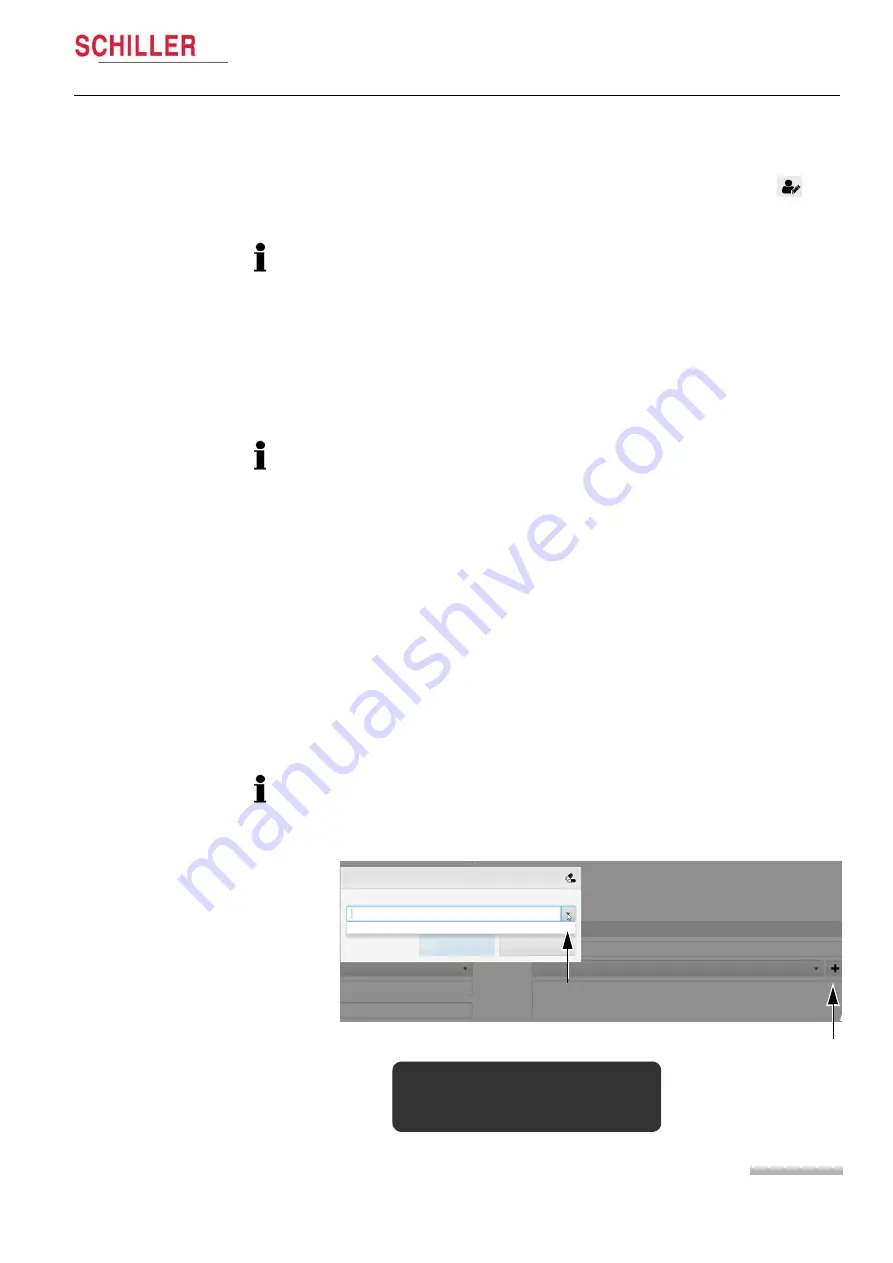
Digitalis

When the Medication field  is selected  an  option  for digitalis is given.  When  this is 
selected  it  can  affect  the  interpretation  of  the  recording  and  you  are  prompted  to 
analyse the recording:

Add medication

Select one of the predetermined medications or enter a new one

Digitalis

Close

Add medication

Medication

Indication

Reinterpretation recommended
Relevant data has changed:

· 

Digitalis medication

Содержание CARDIOVIT CS-104

Страница 1: ...User Guide CARDIOVIT CS 104 Art no 2 511335 Rev a 2 511335 ...

Страница 2: ...LER subsidiary In case of difficulty a complete list of all distributors and subsidiaries is provided on our Internet site http www schiller ch Sales information can also be obtained from sales schiller ch Manufacturer SCHILLER AG Phone 41 0 41 766 42 42 Altgasse 68 Fax 41 0 41 761 08 80 CH 6341 Baar Switzerland Article no 2 511335 Rev a Issue date 3 5 2019 ...

Страница 3: ...ation with other Devices 16 1 14 Extra Precautions for Spirometry 17 1 15 Electrical and Power Source Related 17 1 16 Network Security 18 1 17 Terms of Warranty 18 1 18 Additional Statements 19 1 19 Safety Symbols and Pictograms 20 1 19 1 Symbols Used in this Document 20 1 19 2 Symbols Found on the Device and Recorder 20 2 Introduction 23 2 1 Overview 23 2 2 Configurations 24 2 2 1 CARDIOVIT CS 10...

Страница 4: ... Home Screen 33 3 3 1 Main Menu 34 3 4 Screen Layout 35 3 4 1 Side Bar and Bottom Main Icons 36 3 4 2 Defining the Tables 36 3 4 3 Changing the Column Order 36 3 4 4 Sorting Columns 36 3 5 Selecting Displaying the Recording Device 37 3 6 Connection with the Server if Networked 37 3 6 1 Offline 38 3 7 Recordings 39 3 7 1 Types of Recording 39 3 7 2 Opening a Recording 39 3 8 Display Configuration 4...

Страница 5: ...m the Patient Search Screen 58 4 2 2 From the Recorder Screen 59 4 3 Hookup Screen Electrode Placement and Check 60 4 4 Electrode Check 61 4 4 1 Quality Indication on the ECG Trace 61 4 4 2 Electrode Placement 61 4 5 Standard or Cabrera Lead Sequence 62 4 5 1 Selecting the Lead Configuration 62 4 6 Display Layout and Speed and Amplitude 62 4 7 Pacemaker Detection 62 4 8 Filter 63 4 9 Blood Pressur...

Страница 6: ...8 ECG Recording Analysis 82 8 1 General Analysis Settings and Options 82 8 1 1 Saving after Editing 82 8 1 2 Reports Printing a Recording or Generating a PDF File 83 8 1 3 Direct Print or PDF Generation 83 8 1 4 Rejecting a Recording 84 8 2 Resting ECG Recordings 85 8 2 1 Data Views and Functions 85 8 2 2 ECG Filter 86 8 2 3 ECG Measurements 86 8 2 4 Zoom 86 8 2 5 Amplitude and Speed 86 8 2 6 Chan...

Страница 7: ... Downloading Work Items 111 9 3 1 Worklist Entries 111 9 4 Performing a Worklist Item 112 10 Importing and Exporting Recordings 113 10 1 Importing Recordings 113 10 2 Exporting Recordings 114 10 2 1 Log File 115 11 System Settings 116 11 1 Overview 116 11 1 1 Settings Search 116 11 1 2 Setting Types 117 11 1 3 Elevating a User or Device Setting 117 11 1 4 Changing the User Password 118 11 1 5 Impo...

Страница 8: ...urity 128 11 8 1 Lock Auto User Logout 128 11 8 2 Single Sign On 128 11 9 Licenses 129 11 10 Reports 129 11 10 1 General Company information 129 11 10 2 Header 129 11 10 3 Printer 129 11 10 4 PDF 130 11 10 5 Formats 131 11 10 6 Combine Reports 131 11 11 ECG 132 11 11 1 General 132 11 11 2 Power Line 132 11 11 3 Display Filter 132 11 11 4 Analyser View 132 11 11 5 Print Output and PDF Output 132 11...

Страница 9: ...g 142 13 1 10 Deleting Paired Connections 142 13 1 11 Power Supply 142 13 1 12 Battery Capacity 143 13 1 13 Changing the Batteries 143 13 1 14 MS 12 blue Bluetooth Pairing Procedure 144 13 1 15 Pairing the unit with the PC 144 13 2 MS 12 USB Recorder 146 13 2 1 Function Button 146 13 3 FT 1 Streamer 147 14 Cleaning and Disinfection 148 14 1 Before Cleaning 148 14 2 Cleaning Interval 149 14 3 Clean...

Страница 10: ...e Shooting 156 16 1 Error Messages 156 17 Accessories and Disposables 157 17 1 General 157 17 2 MS 12 blue 157 17 3 MS 12 USB 157 17 4 FT 1 157 18 Technical Specification 158 18 1 CARDIOVIT CS 104 System 158 18 2 Requirements for PC Based Installations 159 18 2 1 CARDIOVIT CS 104 159 18 3 ECG Recorders 159 18 3 1 MS 12 USB 159 18 3 2 MS 12 blue 160 18 3 3 FT 1 Streamer 160 18 4 ECG 160 18 5 Standa...

Страница 11: ... 19 1 Installations using the MS 12 USB 164 19 2 Installation Notes and Requirements 164 19 3 Installation 165 19 4 Exercise ECG and BP Unit 166 19 4 1 Procedure to Connect the USB 232 Serial Adapter 166 19 4 2 USB to RS 232 Serial Adapter 168 19 5 Connection Overview 169 20 Index 171 ...

Страница 12: ...Page 12 Art no 2 511335 Rev a CARDIOVIT CS 104 ...

Страница 13: ...nd pediatric patients able to understand the test instructions 1 3 Optional Use The following options can be sold with the CARDIOVIT CS 104 Exercise ECG standard in some configurations Arrhythmia detection detection of arrhythmias during exercise tests and rest ing rhythm acquisition Vector ECG provides a 3 dimensional view on the electrical activity and adds value to the diagnostic of the hearts ...

Страница 14: ... with all applicable accident prevention regulations and safety regulations The safety reliability and performance of the device can only be guaranteed when the maintenance intervals as stated in the maintenance section are observed 1 8 Organisational Measures Observe the operating and maintenance instructions Keep all instructions in an accessible place for reference when required Make sure that ...

Страница 15: ...cemaker malfunction a distance of at least 25 cm must be kept between the device and the pacemaker as soon as the Bluetooth module is activated Do not place any liquids on the unit Only use the original SCHILLER patient cable and only use accessories and disposables recommended or supplied by SCHILLER Use of other than recommended or supplied parts may result in injury inaccurate information and o...

Страница 16: ...rsion of IEC EN 60601 1 If in doubt contact the technical service department or your local representative Any other equipment used with the patient must use the same common earth as the CARDIOVIT CS 104 Special care must be exercised when the unit is used with high frequency equipment Use the special high frequency SCHILLER patient cable to avoid possible signal interference during ECG acquisition...

Страница 17: ...ing the device without the correctly rated fuse or with defective cables constitutes a danger to life Therefore Do not operate the unit if the earth connection is suspect or if the mains lead is damaged or suspected of being damaged Damaged cable connections and connectors must be replaced immediately The electrical safety devices such as fuses must not be altered Ruptured fuses must only be repla...

Страница 18: ...this warranty is damage caused by an accident or as a result of improper handling The warranty entitles to free replacement of the defective part Any liability for subsequent damage is excluded The warranty is void if unauthorized or unqualified persons attempt to make repairs In case the device is defective send it to your local SCHILLER representative or directly to the manufacturer The manufact...

Страница 19: ...s likely to cause harmful interference in which case the user will be required to correct the interference at his own expense This device contains FCC ID Z64 WL180DBMOD When using the WiFi networking option operation of this equipment requires the prior coordination with a frequency coordinator designated by the FCC for the Wireless Medical Telemetry Service This device complies with Part 15 of th...

Страница 20: ...y or to death For a possibly dangerous situation which could lead to severe personal injury or to death For possibly dangerous situations that could lead to personal injury This symbol is also used to indicate possible damage to property For general safety notes as listed in this chapter Important or helpful user information or safety information 1 19 2 Symbols Found on the Device and Recorder Typ...

Страница 21: ... no longer required must be disposed of in a municipally approved collection point or recycling center Alternatively you can return the equipment to your supplier or SCHILLER for disposal Improper disposal can harm the environment and human health Ni MH Ni MH MS 12 blue battery type AA 2 x Ni MH Use Ni MH conform charger only Do not disassemble mutilate incinerate or heat Do not short circuit a ba...

Страница 22: ...r there is no guarantee that no interference can occur in certain installations If the CARDIOVIT CS 104 causes interferences these can be determined by switching the device off on or by transmitting not transmitting ECG data The user can take the following measures to solve this problem Increase the distance between the disturbed device and the CARDIOVIT CS 104 A minimum distance of 25 cm must be ...

Страница 23: ...an be included SpiroScout SP plus MS 12 ECG Recorder with patient cable Direct or wireless communication Location of isolation transformer option The software is installed on a standalone PC laptop or on a PC incorporated in a device trolley as shown above For all configurations an independent recording device is used that can be positioned for patient convenience For ECG recordings the device is ...

Страница 24: ...ork connection with SCHILLER Server 2 2 3 CARDIOVIT CS 104 Spiro Installed on a PC and not upgradable with any options Spirometry software for FVC SVC and MVV measurment SpiroScout SP plus sensor Network connection with SCHILLER Server 2 3 Options and Features The features and options available with the CS 104 are as follows Network Std Std Std Resting ECG Recorder Std Std Analyse All Recording Ty...

Страница 25: ... list of recordings to be carried out by specific devices Spirometry Spirometry software and SpiroScout SP plus sensor The Spiro option can carry out the following tests FVC SVC MVV A number of American and International normal standards can be selected for predicted value calculation and interpretation Full details of the Spirometry option and operating instructions are detailed in the CARDIOVIT ...

Страница 26: ...other user can view the same recording but no editing functions can be performed If the server becomes disconnected or the network goes down it is not possible to access recordings Any recordings already opened or new recordings taken local ly are stored and then synchronised with the server when again connected 2 6 ECG Recorders There are three ECG recorders available with the CARDIOVIT CS 104 as...

Страница 27: ...uded in the MS 12 USB package 10 lead ECG patient cable snap or banana type IEC or AHA Disposable ECG electrodes set of 100 USB cable assembly Ergo belt 2 6 2 MS 12 blue ECG Recorder The MS 12 blue ECG Recorder is a wireless device that communicates with the CARDIOVIT CS 104 program using wireless bluetooth This recorder is battery has a monitor screen for MS 12 blue settings and ECG display The f...

Страница 28: ...e data is displayed online in the CS 104 application Streaming Switching On Off The unit is switched on and off with the On Off key Battery Charging The battery is charged when the unit is connected to the mains supply The unit can remain connected to the mains supply without damage to either the battery or the unit When the battery is not fully charged and the mains supply is connected the batter...

Страница 29: ...nel The program is opened when the unit is switched on Home screen Patient search Recording search Import Export Settings Help Lock Logout Exit Main menu Worklist Recorder Switching the Unit Off From the main menu select Exit to exit the program and switch off the system You are prompted to confirm switch off 2 7 2 PC Based Installations Click the desktop icon to open the program The login screen ...

Страница 30: ... power indicator lamp is lit all the time the unit is connected to the PC CARDIOVIT FT 1 The FT 1 can be operated form the mains supply via a power supply or battery power Full details are provided in the FT 1 user guide 2 8 4 Isolating the Mains Supply To isolate the power supply to the CARDIOVIT CS 104 or the PC and the MS 12 USB remove the mains plug from the wall socket To isolate the power su...

Страница 31: ...ed when the unit is stationary to prevent the unit from rolling and causing possible injury Lever in the down position wheel locked Lever in the up position wheel unlocked The unit wheels are locked by pressing the foot brake lever down until the wheel is locked The lock is released by lifting the brake lever 2 11 System and ECG Settings System settings time date Device ID etc general system setti...

Страница 32: ...n On page 128 When system authentication is set security can be compromised It is recommended that this setting is only defined for PCs that are single or limited user The function icons on the side and bottom function bars can be set for user prefer ence If a function icon is not available ensure it has been set for display see para 3 8 Display Configuration page 40 User roles and privileges are ...

Страница 33: ...ome screen or Selecting the Workflow from the main menu by clicking on the SCHILLER icon top left of the screen The initial screen when the program is opened home screen tabs and main menu selections can be defined in system settings see para 11 2 6 Workflow page 120 3 3 Home Screen An example of the home screen is shown Patient search Import Export Recording search Worklist Recorder Settings The ...

Страница 34: ...D patient name date of birth or visit ID Enter a new patient Enter the Resting ECG screen Exercise ECG screen or the Spiro recording screen Worklist Enter this screen to search for work items for all or selected patients or groups of patients The work item requirement can be ordered by patient priority order ID etc see para 9 Worklist page 110 Import Export Enter the Import Export screen to import...

Страница 35: ...mber of icons order and the actions that are taken are user defined for each individual screen see para 3 8 Display Configuration page 40 Bottom icons to define actions according to the currently displayed screen The number of icons and the actions can be defined by the user see para 3 8 Display Configuration page 40 Resting Visit ID Last name First name Date of birth Last name Date of birth First...

Страница 36: ...will give a tooltip explanation of the icon 3 4 2 Defining the Tables Right click on any column title to enable disable columns Column data that can be set to include Pat ID Visit ID name blood type ethnicity weight etc Last name First name Patient ID Account Number Alternate ID Blood type Date of birth Ethnicity First name Gender Height Last name Middle name Pacemaker Patient ID Reset Elevate Aft...

Страница 37: ...e user can select the required recording device Select device MS 12 USB Device 1 MS 12 USB Device 2 MS 12 blue Device 1 Cancel 3 6 Connection with the Server if Networked Connection to the SCHILLER Server is indicated in the top right of the screen Hovering over the symbol will indicate the server connection for example Connected to https schillerserver stmary com 8181 SemaServer The network symbo...

Страница 38: ...ffline User name Password Login Exit Click here to check SEMA Server path see para 11 4 Connectivity page 123 In offline mode Any opened recordings or patient data can continue to be edited and viewed but any edits cannot be saved until the server is reconnected the save option is greyed New patients can be defined and recordings can continue to be made and saved These are stored locally and will ...

Страница 39: ...ECG Resting Rhythm Exercise ECG Signal Averaged ECG Rescue PDF only Spirometry Holter blood pressure PDF only Body plethysmography PDF only Diffusion PDF only Provocation PDF only Resistance PDF only Ergo Spiro PDF only Holter ECG PDF only Monitoring PDF only 3 7 2 Opening a Recording To analyse a recording highlight the recording and double click or click the analyse icon in the sidebar Locked Re...

Страница 40: ...dd delete icons as required Click on the Main menu icon again The edit action changes to Save actions Note The number of icons that are available for the side and bottom bars can also be user defined see para 11 2 4 Layout page 120 Patient search local New patient Edit patient Analyse recording Add component Add component Add component Add component Add component Add component Resting ECG Manual I...

Страница 41: ...e of birth or display all patients Recording Search to search for specific type or recording or group of record ings by date patient interpretation type etc or display all recordings Worklist to search for specific worklist recordings The search icon is displayed in the top right of the screen and the search parameter entry field at the top of the screen All recordings patients with the defined pa...

Страница 42: ...ters entered in the search field 3 9 2 Search Results The search results are displayed and opened and sorted as described earlier The recordings that are bold indicate recordings that have not yet been opened Note the number of patients recordings that are displayed after a search has been initiated can be limited if required up to a maximum of 5000 This is set in system settings see para 11 7 2 L...

Страница 43: ... greyed and cannot be changed The Patient ID must be entered to register a patient on the system All other fields are optional and can be entered at a later date as necessary When auto ID is requested for the patient ID the SCHILLER standard Patient ID generator is used SCHILLER uses the universally unique identifier UUID standard The intent of UUIDs is to enable distributed systems to uniquely id...

Страница 44: ... Visit Data In the new patient or edit patient screen below the patient icon the visit icon available to enter visit data The following Visit data can be entered selected Visit Select a previously defined Visit All visit data is populated The visit ID and Ad mitted data cannot be edited the location and referring physician can be edited Define new visit Click the icon by the side of the entry fiel...

Страница 45: ...fficiency past bypass etc Other disease Any other disease that the patient may have e g Diabetes hepatitis gall stones etc Consciousness Define here the patients condition e g somnolent anxious etc Generic Recording Fields Up to three extra fields can be added to the Additional Information area These can be any user defined extra information titles and text can be entered freely or predefined text...

Страница 46: ... Screen Electrode Placement and Check page 60 The IEC or AHA lead cable is set in ECG settings see para 11 11 ECG page 132 4 1 1 Electrode Identification and Colour Code The electrode placements shown in this section are labelled with the colours according to Code 1 IEC requirements The equivalent Code 2 AHA colours are given below R Red RA White Limb L Yellow LA Black F Green LL Red C1 White Red ...

Страница 47: ...nce Shave the areas where the electrodes are to be placed if necessary Thoroughly clean the areas with alcohol or soapy water Let the skin dry before applying the electrodes When applying the electrodes ensure that a layer of gel is between the elec trode and the skin1 5 Check the electrode resistance see para 4 4 Electrode Check page 61 If the electrode resistance is higher than the acceptable le...

Страница 48: ...me horizontal level as C4 C6 white violet V6 brown violet Left mid axillary line on the same horizontal level as C4 L yellow LA black Left arm R red RA white Right arm F green LL red Left foot N black RL green Right foot Auto Interpretation is only generated when standard 12 lead electrode lead config uration is set The lead configuration is set in the lead configuration screen selected at the sta...

Страница 49: ...k Slightly below left clavicle R red RA white Slightly below the right clavicle F green LL red Lower edge of the rib cage or at the level of the umbilicus at the right mid clavicular line N black RL green Lower edge of the rib cage or at the level of the umbilicus at the left mid clavicular line For exercise testing place electrodes C1 to C6 in the same positions as for the standard resting ECG de...

Страница 50: ...ow Fourth intercostal space at the left sternal border C3 white green V3 brown green Midway between sites C2 and C4 C4r white brown V4r brown blue Fifth intercostal space right mid clavicular line C5 white black V5 brown orange Anterior axillary line on the same horizontal level as C4 C6 white violet V6 brown violet Mid axillary line on the same horizontal level as C4 L yellow LA black Left arm R ...

Страница 51: ...8 V2 brown yellow Left of the mid scapular line at the level of C4 C9 C6 white violet V9 V6 brown violet Left paravertebral line at the level of C4 C1 white red V1 brown red Fourth intercostal space at the right sternal border C3r white green V3r brown green Midway between C1 and C4R right side of chest C4r white brown V4r brown blue Fifth intercostal space right mid clavicular line L Yellow LA Bl...

Страница 52: ...llary line at the level of C4 C8 C2 white yellow V8 V2 brown yellow Left of the mid scapular line at the level of C4 C9 C3 white green V9 V3 brown green Left paravertebral line at the level of C4 C4 white brown V4 brown blue Fifth intercostal space on the mid clavicular line C5 white black V5 brown orange Anterior axillary line on the same horizontal level as C4 C6 white violet V6 brown violet Mid...

Страница 53: ...red between the electrode positions Nax and Nst Nehb anterior A between Nap and Nst and Nehb inferior J between Nap and Nax Place the electrodes as follows C1 white red V1 brown red Nst 2nd rib at the right sternal border C2 white yellow V2 brown yellow Nax left posterior axillary line on the back directly opposite Nap C4 white brown V4 brown blue Nap 5th intercostal space midclavicular line cardi...

Страница 54: ... C4r fourth intercostal space C2 white yellow V6 brown violet Fourth intercostal space at the left sternal border C5 white black V5 brown orange Anterior axillary line on the same horizontal level as C4r C6 white violet V6 brown violet Mid axillary line on the same horizontal level as C4r C7 C1 white red V7 V1 brown red Left posterior axillary line at the level of C4r L yellow LA Black Left arm R ...

Страница 55: ...5r Black F Green L Yellow C1 white red V1 brown red Fourth intercostal space at the right sternal border C2 white yellow V2 brown yellow Fourth intercostal space at the left sternal border C3r white green V3 brown green Designated point halfway between C1 and C4r C4r white brown V4 brown blue Fifth intercostal space on the mid clavicular line C5r white black V5 brown orange Anterior axillary line ...

Страница 56: ...r Brown C1 white red V1 brown red Fourth intercostal space at the right sternal border C2 white yellow V2 brown yellow Fourth intercostal space at the left sternal border C3 white green V3 brown green Midway between C2 and C4 C4r white brown V4 brown blue Fifth intercostal space on the mid clavicular line C5 white black V5 brown orange Anterior axillary line on the same horizontal level as C4 C6 w...

Страница 57: ...ch the electrodes in the fifth intercostal space Place all other electrodes in the normal positions C1 white red V1 brown red I X right midaxillary line C2 white yellow V2 brown yellow E Z front midline C3 white green V3 brown green C Y between E Z and A X C4 white brown V4 brown blue A X left midaxillary line C5 white black V5 brown orange M Z back midline on the back C6 white violet V6 brown vio...

Страница 58: ...New Patient icon and enter patient details see para 3 10 Patient Data page 43 Click Resting to enter the Resting and Rhythm recording screens Click Exercise ECG to enter exercise ECG Recording screen Resting Visit ID Last name First name Date of birth Last name First name Patient ID Patient ID Start time Visit ID Validated Type Lock Quick search Search patients by patient ID visit ID name and or d...

Страница 59: ...t not found No patient found by given patient ID Continue with this patient ID No Yes When Yes is selected the patient screen is again displayed and patient data can be entered to define a new patient New Patient Undefined Details Enter a patient ID and then select recording type from the bottom icons The recording is taken and can be stored Patient details can be added later Emergency Resting ECG...

Страница 60: ...de placement graphic is displayed in the left area of the screen and the electrode status is shown in the bottom right information field of the screen If an error is detected the suspected reason for the poor signal quality is displayed see next page Reapply the electrode Auto Rhythm 2 min Search An ECG recording can now be taken ECG quality good Standard 12 Lead Select the lead configuration see ...

Страница 61: ...rodes are not properly connected Please check that all electrodes are placed at the correct position Electrode Off 4 4 1 Quality Indication on the ECG Trace The signal quality is also indicated by the colour of the ECG trace as follows Green Trace Good signal Yellow Trace Poor signal quality you should be able to make a recording but the indicated lead s have an electrode that is higher resistance...

Страница 62: ...tion is only possible when Standard 12 lead is set 4 6 Display Layout and Speed and Amplitude Display Layout Speed and Amplitude Display Layout Select the Display layout with the top icons Speed and Amplitude The speed and amplitude of the ECG trace are displayed and set in the top left of the screen when the settings icon is clicked 4 7 Pacemaker Pacemaker pulses can be enabled disabled when the ...

Страница 63: ...er page 132 The side bar and bottom navigation buttons are user set If the Filter Pacemaker or any other icons are not displayed they can be set for display by clicking edit icons see para 3 4 1 Side Bar and Bottom Main Icons page 36 4 9 Blood Pressure 64 Blood pressure can be entered by clicking the Blood pressure measurement in the top left of the screen When clicked you are prompted to enter th...

Страница 64: ...1 Discarding a Recording Discard Click Discard to return to the ECG acquisition screen without saving the recording Confirmation that the recording is not to be saved is requested Discard recording The current recording will be discarded Do you want to proceed No Yes The Discard icon is only available when defined in the screen layout see para 3 8 Display Configuration page 40 ...

Страница 65: ...een see para 4 2 Entering a Recording Screen page 58 Resting ECG Start time Visit ID Validated Type Lock Order ID Resting Rhythm Resting ECG Exercise ECG Found 50 of 66 Limit 50 3 Click Resting ECG icon 4 Check the ECG and ensure a good trace 5 Take an auto mode recording as follows Press the Auto key Auto If using the MS 12 USB pressing the Start button the button will be blue and blinking will p...

Страница 66: ...ed before taking a recording 5 1 1 ETM Sport Option The ETM Sport diagnoses abnormalities in athletes in a resting ECG that otherwise would not be diagnosed The ETM Sport icon must be clicked before an Auto recording is made Auto Rhythm 10 min ETM Sport Search Indicates if ETM Sport is on or off ETM Sport is for resting ECG only and when on Rhythm recording is disabled When set the Seattle criteri...

Страница 67: ...ting ECG Start time Visit ID Validated Type Lock Order ID Resting Rhythm Resting ECG Exercise ECG Found 50 of 66 Limit 50 3 Click Resting ECG icon 4 Check the ECG and ensure a good trace 5 Press Rhythm Rhythm 2 min 6 Select the recording duration in the dialogue Rhythm length Show duration dialogue Start Cancel Rhythm Settings The default rhythm length and whether or not the duration dialogue is d...

Страница 68: ...Manual events can be entered during the test see following Click Stop to stop the recording before the defined time In the first 10 seconds of the recording the Stop button states Cancel to cancel the recording in the initial period 6 1 1 Arrhythmia option When the Arrhythmia option is enabled an extra field is given to display the Ventricular Ectopic Beat Rate VEBR This gives the number of ventri...

Страница 69: ...row to the side to select predefined events see note and click OK Events will be referenced in the recording see para 8 3 3 Events page 97 Manuel event text can be pre entered if required and available for selection when the arrow by the event entry is clicked The manual event wording is defined in system settings see para 11 13 Rhythm ECG page 133 6 3 At the End of a Rhythm Recording The recordin...

Страница 70: ...ample of falling on the treadmill Ensure the patient is aware of the location of the emergency stop knob and its use Ensure that the resting ECG confirms that the patient is able to carry out an exercise ECG Ensure a charged defibrillator is to hand when carrying out an exercise test To avoid possible interference from the Ergometer when carrying out an exercise test it is recommended that both th...

Страница 71: ... search Recording search Import Export Settings Help Lock Logout Main menu Exit Bicycle Treadmill Ergo device Bicycle model Bicycle port Treadmill model Treadmill port Speed unit NIBP device NIBP port Enable SpO2 trend Resting ECG Scale Rhythm ECG General Scale Events Exercise ECG General Events Scale Recorder Ergo Devices 7 3 2 Protocols Define the protocols that can be selected for the test Move...

Страница 72: ...in the settings section see para 8 4 Exercise ECG page 99 7 4 Exercise Test Procedure 1 Prepare the patient and connect the electrodes see para 4 1 Placing the Elec trodes page 46 2 If using the MS 12 blue secure the MS 12 USB ECG Recorder to the patient using the ergo belt 3 Enter the Recording screen see para 4 2 Entering a Recording Screen page 58 4 Click Exercise ECG icon Exercise Check the EC...

Страница 73: ...otocol has been selected the timer display shows Sitting The pre phase time counter displays pre phase elapsed time after the standing or sitting indication During this period the blood pressure cuff can be applied and for example a BP measurement taken SpO2 measurement entered J point measuring point set lactate measurement entered etc After a period of 10 seconds a reference complex is displayed...

Страница 74: ...se can com mence when it is felt the patient is ready Note The warm up phase optional and is defined in the protocol If a warm up phase is defined the next step after the pre phase is warm up If warm up has not been de fined for the protocol the work stage is entered directly after the pre phase Work 3 Click the Work button to commence the test according to the protocol Note The maximum duration o...

Страница 75: ...CG when using a bicycle ergometer Trend Load Heart rate Blood Pressure METs Recovery Search 12edmf673kl 2421243 72 Fred Jones Test 37 years Male Work Next Hold Step 1 Trend ST Amplitude ST Slope Lead and J point Click to redefine Load applied Click the arrows to decrease Increase load Test Control Buttons Individual lead ST Amplitude Click on graph to remove display legend as required ...

Страница 76: ...ing Do you want to discard the current recording Discard Cancel 7 5 2 Information and Settings Panel Heart Rate Averaged over 4 beats The percentage of current heart to target heart rate is displayed after the heart rate the formula used to define the target heart rate is defined in system settings see para 11 14 Exercise ECG page 133 120 48 of 170 82 If the target is exceeded the Heart rate indic...

Страница 77: ... ECG real time display This is enabled disables in system settings see para 11 14 Exercise ECG page 133 The reference complexes are defined in the warm up phase The reference complex and the J point can be changed at any time see ST meas urement previous page The ST amplitude and slope measurements are shown at the top right of the zoom complex The lead and J point are displayed top left of the zo...

Страница 78: ... 50s before the end of work recovery step or instantly if work recovery stage is shorter than 50s A BP measurement can also be taken at any time during the test as follows Initiating a BP Measurement from an Attached Device Measurement in progress Initiate BP Measurement When an NIBP device has been defined see para 11 14 Exercise ECG page 133 blood pressure measurements are initiated by clicking ...

Страница 79: ... the icon must be set for display in the side or bottom icon bar for display see para 3 8 Display Configuration page 40 Rating of perceived exertion RPE is a subjective indication of patient exertion The entered RPE is shown on the final report Select RPE from the side or bottom line icon bar Enter RPE 1 20 Cancel Ok 7 5 8 Events To enable manual events the icon must be set for display in the side...

Страница 80: ...se decrease elevation or left right to decrease increase speed 7 5 10 Bicycle Load Control Bicycle load can be manually increased or decreased from the current values at any time in the test in the same manner as for a treadmill Click the left right keys to decrease increase the load If a keyboard is attached the arrow keys can also be used to change the load speed elevation as follows If a protoc...

Страница 81: ...is clicked Finish current stage before entering recovery stage control button dis plays Init Recovery Init Recovery Press Init Recovery button to enter the recovery stage The current exercise stage is completed before the recovery stage is entered The button changes to Recovery to directly enter the Recovery stage At the end of the stage the recovery stage is entered the recovery stage time is dis...

Страница 82: ...bled an icon appears in the top right of screen that enables selection of another recording from the same patient 05 03 2017 11 37 09 04 2017 15 12 11 03 2017 11 42 02 02 2017 11 57 15 01 2017 15 12 17 12 2016 14 49 Standard 12 Lead 8 1 1 Saving after Editing If you wish to save any changes to a recording click the Save button If you attempt to leave a recording after editing without saving a prom...

Страница 83: ...ts Cancel Averages Grid 25 25 mm s Averages Grid 50 25 mm s Averages Wide 50 25 mm s Rhythm 10s 25 mm s 2p Rhythm 5s 25 mm s 2p Vector Loops Panorama 25 mm s H1 Format 50 12 5 mm s Rhythm 10s 25 mm s Rhythm 5s 25 mm s Rhythm Grid 25 mm S The data for selection is defined in settings see para 11 10 Reports page 129 Combined reports can be user defined to group any combination of options in a single...

Страница 84: ...mpted to confirm Reject recording Are you sure you want to reject Once rejected recording cannot be un rejected Yes No When a recording has been rejected the following happens A line is set through the recording entry The recording is set to Read Only When the recording is opened the following dialogue is displayed Recording Rejected Caution This recording has been rejected for quality reasons The...

Страница 85: ...mplitude and timing measurements for all channels Remeasure In this screen you can edit the measuring points A zoomed view of a selected lead is given and measuring points can be edited and a new interpretation generated after editing Visual Comparison One recording from the same patient can be compared with the current recording Recording detail General and recording specific patient data see par...

Страница 86: ...ce measurement and drag the mouse to display measurements in relation to the start point The measurement remains on the screen until the mouse is again clicked and a new measurement can be taken The measurements calculated are as follows Amplitude in mV Time in seconds Slope in mV s 8 2 4 Zoom Click the zoom icon in the top left of the screen to display a zoom view above the selected section 8 2 5...

Страница 87: ... 8 2 8 RR Intervals In the two Rhythm views and on the rhythm strip in the averages view and sequential view interval measurement and edit is possible The Interval Measurement tool is enabled in the sidebar Clicking on any vertical interval marker the cursor changes to an adjust symbol adjusts the interval The current interval in ms and the heart rate is displayed by the side of the blue measureme...

Страница 88: ... is selected in the top left of the screen All other leads are greyed for reference Highlighted lead and selection Manually adjusted values are indicated blue Search Save No interpretation Intervals Axes 62 bpm 123 83 Remeasure icon Click on any of the measurement markers This displays an enlarged view of the selected area Move the marker to redefine the measurement point When a measurement point ...

Страница 89: ...be adjusted see para 8 2 8 RR Intervals page 87 Because changing the global measurement points can affect the interpretation when the measurement point is moved you are prompted to reinterpret the recording The auto symbol appears in the top right of the screen indicating that reinterpretation should be considered and the following message is given detailing the editing changes that have been made...

Страница 90: ... more details interpretation date institutes etc Editing Enter text as required Enter a character s and click the interpretation template icon or press CTRL space bar to display interpretation templates and acronyms Trigger an auto ETM interpretation Validation Click the tick box to validate the interpretation When an interpretation has been validated no further changes can be made to the interpre...

Страница 91: ...cording to the ETM Sport criteria is given Filter Store recording Discard ETM Sport criteria Normal ECG in Athletes None of the criteria are observed Created by Doc 5 Wyl 12edmf673kl 2421243 72 Fred Jones Test 21years Male Sinus rhythm Normal electrical axis Normal eECG Normal eECG in athletes Borderline diagnosis any one criterion in first 5 identified Abnormal diagnosis two or more criteria in f...

Страница 92: ...er Such hypertrophy is usually the response to a chronic volume or pressure overload The two most important pressure overload states are systemic hypertension and aortic stenosis The major conditions associated with left ventricular volume overload are aortic or mitral valve regurgitation and dilated cardiomyopathy Ventricular septal defects cause both right and left ventricular volume overload wh...

Страница 93: ...limb leads 20 mm S in V1 or V2 30 mm R in V5 or V6 30 mm 3 ST T Abnormalities ST T vector opposite to QRS without digitalis ST T vector opposite to QRS with digitalis 3 1 Negative terminal P mode in V1 1 mm in depth and 0 04 sec in duration indicating left atrial enlargement 3 Left axis deviation QRS of 30 or more 2 QRS duration 0 09 sec 1 Delayed intrinsicoid deflection in V5 or V6 0 05 sec 1 ECG...

Страница 94: ... of a vector are indicated by three spatial coordinates X Y and Z The shape the direction of the rotation the orientation and the speed of rotation of the individual loops are the predominant factors for the analysis of the vector cardiogram Vector loops are represented spatially and projected on the following three planes Horizontal plane X Z Frontal plane X Y Sagittal plane Z Y The P wave QRS an...

Страница 95: ...and interpretation are displayed at the side Note It is only possible to select recordings that are older than the original for comparison and the recording with which the original is compared is read only Select recording when a patient has more than one other recording toggle though with the arrow keys Search Save Intervals Axes Intervals Axes No interpretation Previous ECG 7 days older 12 34 55...

Страница 96: ...backward by clicking to the left or right of the time cursor The events column shows manually entered events Click on any event to jump to the recording section in the rhythm screen Move the cursor in the ECG trace to the required position and click the add event icon and enter the event annotation as required The event is referenced in the event column The width of the time position cursor indica...

Страница 97: ...NIPB measurement manual NIBP measurement Blue Reference marker Gold Symptom Red Arrhythmia technical alarm vital alarm trip high vital alarm trip low Technical alarm 0 04 10 Technical alarm Priority Low Event Details Hover over the event to display the event details To keep the event details displayed click on the event Manual event Add event Adding a Manual Event Click the manual icon in the side...

Страница 98: ...RDIOVIT CS 104 8 3 4 Events View Click the events icon in the side bar to view all events No interpretation Time Type Description Additional info Click to add interpretation Time Description Manual events Heartrate trend Click on an event to display the ECG trace where the event occurred ...

Страница 99: ...m Search Save Double clicking in the step will enter the ECG step view to display the last 10 seconds of the selected stage Created by default Stage load with BK_TEST1 protocol from 50 W to 150 W for a duration of 10 01 mm ss BP increase from 0 0 to max 0 0 increase in heart rate from 79 min to max 109 min Achieved heart rate 80 of target In all screens where step data is displayed in the example ...

Страница 100: ...working capacity PWC is based on the expected load of the patient that will result with the heart rate of 130 150 170 min The measurement is derived from the linear relation between the heart rate during submaximal exercise and exercise load and correlates with VO2max The formula used is as follows Patient Age 18 Expected load 0 Patient Age 18 and 42 Expected load W 3 Patient Age 42 Expected Load ...

Страница 101: ...e dyspepsia measurement entered during the test HR The maximum heart rate measured in the step Jxx mm Jxx mV s The averaged ST elevation at the end of the stage in mm or mV s The point where the ST is measured can be user defined see J point set next page Lact mmol l Lactate measurement entered during the test Load Load applied during the test METS METS Pain Subjective pain measurement entered dur...

Страница 102: ...lue and edit as required Load W HR bpm BP mmHg Editing a Blood Pressure Measurement or Entering a New Measurement To edit a BP measurement click the edit icon and then click on the measure ment in the graph To enter a new BP measurement click the edit icon and click in the graph where the BP measurement is to be positioned Enter blood pressure Systolic Diastolic OK Cancel 8 4 3 ST Measuring J poin...

Страница 103: ...rk recovery load and heart rate at the end of stage Time from the beginning of the test to the beginning of the stage Also included are BP SpO2 Borg rating VES count and Lactate if entered and METs The two red and blue figures in the top right of every averaged complex give the ST elevation mm and slope mV s 123 79 SWT Jones Fred 49 years Undefined Search Save Warm up Work 1 Dur Load HR SpO2 Borg ...

Страница 104: ...ne in grey Reference complex Isoelectric reference 8 ECG Recording Analysis 8 4 Exercise ECG Page 104 Art no 2 511335 Rev a CARDIOVIT CS 104 Isoelectric and Reference curve Displaying the Average Complexes for Pre test Stages Max load ST Max and Recovery Stages Click the max average icon in the side bar to display average ECG complexes for Pre test Max load ST max during the work stages Recovery a...

Страница 105: ...e event to keep details displayed The events are colour coded for the type of event see para 8 3 3 Events page 97 Select next previous stage with arrow icons Define Rhythm lead Created by default Time Description Drug administered Drug administered Stage load with BK_TEST1 protocol from 50 W to 150 W for a duration of 10 01 mm ss BP increase from 0 0 to max 0 0 increase in heart rate from 79 min t...

Страница 106: ... displays all leads in a single column and Rhythm 2 in two columns Search Save Manual events Work 2 6 9 Dur Load HR SpO2 Borg Time METs BP Lact VES Select next previous stage with arrow icons The stage changes automatically as the recording is progressed Created by default The width of the time position cursor indicates the time segment of the waveforms displayed when the speed is changed the widt...

Страница 107: ...yed ST elevation and slope see para 8 4 4 Average View page 103 123 79 SWT Jones Fred 49 years Undefined Search Save Created by default Work 5 9 Dur Load HR SpO2 Borg Time METs BP Lact VES Select next previous stage with arrow icons Stage load with BK_TEST1 protocol from 50 W to 150 W for a duration of 10 01 mm ss BP increase from 0 0 to max 0 0 increase in heart rate from 79 min to max 109 min Ac...

Страница 108: ... Stage load with BK_TEST1 protocol from 50 W to 150 W for a duration of 10 01 mm ss BP increase from 0 0 to max 0 0 increase in heart rate from 79 min to max 109 min Achieved heart rate 80 of target The rhythm leads are selected in the side bar 8 4 9 Step Measurements Click the Step Measurements icon to display the averaged measurements of all leads over the selected stage 123 79 SWT Jones Fred 49...

Страница 109: ... display the ST measurements for every lead and every step 123 79 SWT Jones Fred 49 years Undefined ST amplitude mm 8 4 11 ST Trend View Click the ST Trend view icon to display the ST measurements in a graphical format for every lead The blue line indicates the amplitude in mm The red line gives the slope in mV s 123 79 SWT Jones Fred 49 years Undefined ...

Страница 110: ...he type of recording to be carried out priority and start time etc can be specified and work items can be targeted for specific units or groups of units Work items are fetched via the SCHILLER Server 9 2 The Worklist Screen From the home screen or main menu select Worklist The worklist screen is shown Resting Priority Last name First name Date of birth Patient ID Visit ID Order ID Recording Type P...

Страница 111: ...ing search criteria Recording type Any Resting Rhythm Exercise Spiro Priority High Routine Stat immediate Undefined Patient ID Order ID Visit ID Quick Search Quick search provides the following search criteria Patient ID Visit ID Last name First name Date of birth 9 3 1 Worklist Entries The detail of each work item entry is given in the columns Recording Type Resting ECG Resting Rhythm ECG or Exer...

Страница 112: ...en 2 Click the recording button at the bottom of the screen The acquisition screen is entered for the recording type defined When a recording type is specified in the work item only that type of recording will be able to be carried out and only that recording icon will be able to be selected Other buttons will be greyed 3 Carry out the recording The recording is sent to the ordering authority when...

Страница 113: ...Export Main menu 1 Click the SCHILLER icon top left of the screen to display the main menu options and select Import 2 Enter the directory from where the recording s are located and click Start import Import path Select a directory to import from File name Last modified Patient Visit Intervention 1230945_sw 17 09 2017 resttestecg vis010717 The recording s must be located in a folder it is not poss...

Страница 114: ...on Enable anonymisation Replace patient ID and Visit ID with unique random ID Last name mask First name mask Pat ID mask Root path Sub folder name Search recordings by patient ID visit ID last name first name and or data of birth Anonymise and mask patient name see text Destination and sub folder see text Format Found 5 of 5 Limit Anonymise When Enable anonymisation is checked the patient name is ...

Страница 115: ...ask is entered this would result in a first name mask of Fr ck Destination and Sub Folder Placeholders can be used when defining the storage location and these are replaced with the actual value during the action For example when defining the destination path for Export Recording Destination root path could be set to C Desktop Export The sub folder is set to pid The patient of the recording to be ...

Страница 116: ...nu and select Settings General Station Font size Screen resolution Layout Recording selector Initial activity Medication Regional Date time Language Units Search Reset user settings Reset device settings Settings Import Export Settings Patient ID System Connectivity SEMA server Custom fields Simulation data Change Password Recorder view Scroll through the settings to display all settings 11 1 1 Se...

Страница 117: ...at it has been applied to all users Patient search Quick search Define which search is active per default when opening patient search In some user settings on the screen for example when defining tables the user settings can also be elevated Last name First name Patient ID Account Number Alternate ID Blood type Date of birth Ethnicity First name Gender Height Refresh Elevate Right click on a colum...

Страница 118: ...Settings If a number of installations are required to have the same settings for example a settings import export function is available to define the global settings The settings are defined for one installation exported to a USB stick and can then can be imported to any other installation Exporting Settings 1 Define all settings 2 Click the Export Settings icon 3 Define the export directory for e...

Страница 119: ...ned Overwrite system defaults When this is selected a new fields is displayed to en ter the dots per inch DPI The blue and red squares change according to the set ting User system defaults Use the resolution defined for the operating system Optimise for screen Because the pixel calculation can be different on screen siz es and resolutions it is sometimes not possible to even the grid and trace whe...

Страница 120: ...eview screen When enabled an arrow appears in the top right of the screen for selection of other recordings without going back to the patient or recording screens see para 8 1 General Analysis Settings and Options page 82 11 2 6 Workflow Initial Activity Initial screen on Startup select between Home screen Patient search Recording search Recorder new patient entry screen Worklist networked install...

Страница 121: ...s To avoid the possibility of false data and diagnosis being attributed to an actual patient do not activate this function in a working environment 11 2 10 Recorder View Here the settings for how the ECG is displayed on the screen are defined during acquisition Settings include background and text colour and trace colours and thickness The trace colour can be defined for the quality of the signal ...

Страница 122: ... Cm metres or inches Speed Km h or mph Altitude metres or feet Temperature Degrees Centigrade o C or Fahrenheit o F 11 3 4 Patient ID System When a new patient is defined the Patient ID can entered manually or can be generated automatically or to a specific format The following ID formats are available None the patient ID is entered in any format required SCHILLER standard a patient ID generator i...

Страница 123: ...HILLER Update Server SUS The update server screen gives the current server connection settings and details This is usually defined on installation The path is defined in the host field and the port number default 8080 As the host is defined the URL path is automatically entered in the URL field When the Test server connection button is clicked the program pings the server to check connection as de...

Страница 124: ...oad Cancel When the program has been downloaded you are prompted to install Start Update Update file downloaded successfully Do you want to update now Yes No The program closes and the update starts You are prompted to confirm and a progress bar is displayed When installed click the CS 104 icon to open with the updated software Further details of the SUS are provided in the SUS configuration Guide...

Страница 125: ... configuration 11 5 2 Export Interface Select the output interface to be used Selected between Disabled no import export interface used GDT SEMA2 PDF HL7 Export Directory The directory used for working communication The drive and the directory used to access exported files This information must be the same as in the EMR configuration Attach PDF Check this box to additionally generate a PDF file of...

Страница 126: ...d using these IDs it is essential that all IDs be unique especially in the case of multiple devices for example 2 ECG devices from the same manufacturer File extension use Select auto increment or static When auto increment is selected the file extension will increase by one every export that is 0001 0002 etc Export Measurements This setting is how and where to export the measurement table and is ...

Страница 127: ...t is available and can be selected by the user in the interpretation screen of the recording 11 6 3 Custom Acronyms Only with the advanced interpretation option Enter user defined interpretation acronyms are required each line represents and custom acronym that can be selected in the interpretation screen 11 6 4 Templates Only with the advanced interpretation option When more text acronyms or opti...

Страница 128: ...riod the program is locked and the user must login again to enable the program Check the Lock enabled box to enable the lock screen setting When this box is checked the lock screen time can be defined up to 86400 seconds 24 hours 11 8 2 Single Sign On When system authentication is set security can be compromised It is recommended that this setting is only defined for PCs that are single or limited...

Страница 129: ... logo on a report The file must be a jpg bmp etc The file can be any size and the program will scale the image to fit Enter additional company information address as required Rhythm Mode This is a general setting for all recording types printing 10s rhythm strips Define the rhythm mode to be sequential or simultaneous QTC calculation Select the default calculation between Bazett Fridericia Framing...

Страница 130: ... deviceid Device ID recordingdate Recording date yyyyMMdd HHmmss recordingtype Recording type reportformat Report format name Show file dialogue when generating PDF Check this box to display a prompt every time a PDF file is generated to select the storage location of the PDF file f this box is not checked the default path and name is automatically set see above Conformance PDF Conformance select ...

Страница 131: ...en selected in the Print PDF selection 11 10 6 Combine Reports Recording Type Select between Resting ECG Resting Rhythm EECG or Spiro and Er goSpiro SAECG or Rescue Report name Any suitable name can be entered here for the report This is the name that will appear in the options when a recording is to be printed or a PDF generated Available and Selected Formats In the left column are all the availa...

Страница 132: ...ng on the recording device an ECG recorded in auto mode is stored unfiltered It is therefore possible to record and print the stored ECG either with or without a filter applied In this screen the filters available can be defined for resting ECG and exercise ECG The filter settings are Off 25 HZ 40 Hz and 150 Hz and for exercise only RNSF1 Any combination of filters can be enabled and applied with ...

Страница 133: ...g The event entry is available during the recording when the Manual event button is clicked see para 6 2 1 Manual Events page 69 11 14 Exercise ECG 11 14 1 General ST Trend Define the settings for the ST trend graphs at the top of the screen Table Trend split This defines the relative sizes of the Table trend ratio de fine for preference Show ST Trend check as required to display the ST trend grap...

Страница 134: ...stage is entered set by user Average complex Check this box to show the average reference complex see para 7 4 Exercise Test Procedure page 72 Show chart legend Check this box to display the legend for the three graphs in the upper area can be enabled disabled see para 7 5 During the Test page 75 11 14 3 Scale Set the default amplitude and speed scale for the following Rhythm Continuous multi line...

Страница 135: ...d for selection in Protocols at the start of the test The procedure to define a new protocol is a follows Ergo device Protocol name Ramp Warmup step Step Duration Load W NIBP Exercise 16 00 min Work 1 Work 2 Work 3 Work 4 Recover 1 Recover 2 Bicycle Dr Freds athlete trial Add step Remove step Total work time displayed as stages edited Check to take a BP measurement during the stage see note below ...

Страница 136: ...x to initiate a BP measurement for that stage or display the BP input screen for manual entry Note A BP measurement is taken 10s after the pre phase and after the warmup phase when a warmup phase has been set in the protocol A BP measurement is initiated when checked for a stage as follows 50s before the end of work recovery step OR instantly if work recovery stage duration is less than 50s 8 Defi...

Страница 137: ...ivileges for the user roles can be edited by the administrator Every user is assigned to a specific Role New users can be added at any time and existing users edited or removed From settings select User Management to show the user management screen Users list of all defined users Start export User detail Enabled User name User Roles list of all user roles defined by system Privileges privileges de...

Страница 138: ...1 In the Users column click the new user icon 2 In the User detail column Enter user name and define password retype password to confirm the user name and password are required for login Define the User Role and associated privileges Click save to save changes or return to return with saving changes 12 3 Deleting or Editing a User 1 In the Users column highlight the user To delete click the trash ...

Страница 139: ...nction of the highlighted menu item 13 1 2 Switching the Unit On To switch on the unit press the control button 13 1 3 Switching the Unit Off The unit can be switched off from the main menu and from the electrode screen 13 1 4 Switching Off from the Main Menu Highlight the off icon and press and hold the control button for approximately 1 5 seconds The off icon is displayed flashing in the middle ...

Страница 140: ...e control button is released during the switch off period when the time line is displayed switch off is cancelled and the unit continues to transmit 13 1 6 Display The display provides limited information and options for unit functions The main menu displayed when the unit is switched on displays the following a c b a Software version The software version of the unit is displayed in the top line b...

Страница 141: ...esistance that is within tolerance to provide a good recording is shown as a thick circle When a high resistance electrode is detected either before the electrode is connected or if the electrode becomes dislodged or becomes high resistance during a recording the high resistance electrode symbol is displayed showing the lead designation When all electrodes are connected the screen displays the ECG...

Страница 142: ...er in this user guide see para 13 1 14 MS 12 blue Bluetooth Pairing Procedure page 144 Highlight the Bluetooth disconnect icon and press the control button for 1 5 seconds The hourglass icon is displayed briefly while disconnection is in progress After disconnection the main menu is displayed and paired connections are lost 13 1 10 Deleting Paired Connections 13 1 11 Power Supply The MS 12 blue co...

Страница 143: ...ion has stopped and the batteries must be exchanged 13 1 13 Changing the Batteries Battery Removal 1 Slide the battery compartment cover away from the unit apply pressure to the cover and push away from the unit 2 Lift the battery removal ribbon and Neg Pos Battery removal ribbon remove the batteries Replacing the Batteries Only use rechargeable batteries Ensure the batteries are fully charged whe...

Страница 144: ... add a device from this menu option 2 The PC will search for any bluetooth devices in range and the PC displays the search screen 3 During the period when the PC is searching switch on the MS 12 blue unit and select the bluetooth option From the main menu highlight the bluetooth settings icon and press the control button for approximately 1 5 seconds until the Bluetooth screen is displayed Highlig...

Страница 145: ... as follows On the MS 12 blue with the tick box highlighted as shown press the control button for approximately 1 5 seconds At the PC click next Depending on the bluetooth driver and this screen displayed Windows may ask for a password If this is requested a password of 0000 can be entered 8 A confirmation message is displayed that the unit has been registered with Windows ...

Страница 146: ... USB ECG Recorder as follows White Outline and Unlit MS 12 USB is not connected to the PC or the PC is switched off Illuminated Light Blue MS 12 USB connected to the PC and powered switched on Light Blue Blinking Button is active and in the Resting ECG Screen pressing the function button will initiate an auto mode ECG It is the same function as selecting the Auto icon Auto in the program In the Rh...

Страница 147: ...layed on the screen This changes to Streaming when transmitting data Switching On Off The unit is switched on and off with the On Off key Battery Charging The battery is charged when the unit is connected to the mains supply The unit can remain connected to the mains supply without damage to either the battery or the unit When the battery is not fully charged and the mains supply is connected the ...

Страница 148: ...cable contacts must not come in contact with soap or water Do not immerse in liquid when cleaning Do not spray the unit directly Only clean the device and cable with a damp cloth slightly moistened not wet on the surface only If liquid does penetrate the unit switch it off immediately and send it to SCHILLER for testing The patient cable and other cable assemblies must not be exposed to excessive ...

Страница 149: ...vice Clean the recorder with a damp cloth slightly moistened not wet on the surface only Use cleaning agents that are mild and diluted with water that are suitable for PC polycarbonate approved cleaning solutions are listed following Use a clean lint free cloth moistened with detergent and wipe the unit to clean Leave to dry in the air for at least 30 minutes Ensure liquid does not get into connec...

Страница 150: ...ing solution run into or accumulate in connector openings latches or crevices If liquid gets into connectors dry the area with warm air 14 5 Cleaning Solutions 14 5 1 Construction Material Ensure that all cleaning materials used on the MS 12 USB ECG Recorder and cable assemblies are suitable for the material used in its construction The list of cleaning solutions and disinfectants are provided as ...

Страница 151: ...ia and viruses Please refer to the manufacturer s information Use commercially available disinfectants intended for clinics hospitals and practices to disinfect the device Disinfect in the same way as described for cleaning previous page 14 6 1 Approved Disinfectants Isopropyl alcohol 50 Propanol 35 Ethyl hexanal Aldehyde 2 4 Ethanol 50 all products that are suitable for PC ABS plastic 14 6 2 Reco...

Страница 152: ... alcohol Virex Sani Master Sani Cloth Ascepti or Clorox wipes HB Quat Conventional cleaner e g Fantastic Tilex etc Conductive solution Solutions or products containing the following Acetone Ammonium chloride Betadine Chlorine wax or wax compound Ketone Sodium salt Using these products or products containing similar components can cause discoloration of the product corrosion and reduction of the pr...

Страница 153: ...test according to IEC EN 62353 Qualified service personnel 15 1 Visual Inspection Inspect the unit and cable assemblies for the following Device casing not broken or cracked Electrode cable sheathing and connectors undamaged No kinks abrasion or wear Do not use if the unit or any cable assembly or accessory is damaged Defective units damaged cables or damaged accessories must be replaced immediate...

Страница 154: ... if applicable correctly mark label each individual component Observe the environmental conditions for storage and transportation 15 6 Disposal 15 6 1 Electronic Parts At the end of the life cycle the device and accessories must be disposed of in accordance with the applicable international and national waste control regulations for electronic components Parts must be collected separately from ord...

Страница 155: ...and connectors undamaged No kinks abrasion or wear Basic Functional Check page 153 Ensure the ECG trace is displayed Check the electrode hook up screen displays that the electrode is high re sistance Date Of Inspection and Inspector 15 7 2 Every 24 Months Safety and Functional Checks page 154 Confirm the date of the factory inspections and test If the unit is due for the factory in spections and t...

Страница 156: ... Ensure mains filter is correct for mains supply see para 11 11 2 Power Line page 132 If the trace is still noisy call your local SCHILLER representative Control icons buttons or options not displayed Options not licensed Configuration does not sup port option Control action view but tons not defined for view Check licensing options see para 11 9 Licens es page 129 Define for view see para 3 8 Dis...

Страница 157: ...es incl 6 suction electrodes 4 clamp extremity electrodes and ECG electrode gel 50ml 2 155025 Blue Sensor Disposable ECG Electrode ø 48mm Set of 25 2 100060 Ergo belt 17 2 MS 12 blue 2 400225 10 wire patient cable banana connection IEC 2 400228 10 wire patient cable clip type IEC 2 400222 10 wire patient cable snap type IEC 2 400224 10 wire patient cable banana connection AHA 2 400229 10 wire pati...

Страница 158: ...0 x2 Mic in Line out SD card reader Back Panel USB 2 0 x4 RJ 45 x2 HDMI Display Port DP RS 232 x2 4 pin dc power input external power supply External switch connector used for On off button on back panel of trolley Monitor Power Supply 23 8 full HD LCD LED Rating 12 Vdc 2 5 A adaptor source refer to user manual Network LAN Controller 2x Realtek RTL8111G WOL PXE supports Teaming Ethernet Fast Ether...

Страница 159: ...intout on normal paper with inkjet or laser printer Network Standard 100 Mbit s Ethernet or standard WLAN configuration Bluetooth Bluetooth 2 0 or higher or external bluetooth transceiver MS 12 blue only 18 3 ECG Recorders 18 3 1 MS 12 USB Dimensions and Weight Height Width Depth Weight 95 x 62 x 14 mm 140 gm including USB cable USB Cable Length USB cable for PC connection unit power and data tran...

Страница 160: ...ECG General Leads ECG analysis frequency ETM Resting ECG storage Time offset between ECG channels ST measurements J and post J point Signal processing technique QRS detection and analysis ECG output Heart rate Arrhythmia Resting rhythm ECG Re analysis ECG interpretation Standard Cabrera NEHB Frank right precordial left posterior balanced user configurable Simultaneous recording of all 10 active el...

Страница 161: ...tions storage and transport Temperature transport Temperature storage Relative humidity storage and transport Pressure storage and transport 10 C to 50 C 14 F to 122 F 5 C to 50 C 41 F to 122 F 10 to 95 non condensing 500 to 1060 hPa 18 7 Program Information Home screen Patient search Recording search Import Export Settings Help Lock Logout Exit Main menu Inbox From the main menu click the Help ic...

Страница 162: ...og Information Click the Log icon to display program history data This is for service personnel only 18 9 End of Life Disposal At the end of unit life do not dispose in household waste MS 12 USB units must be disposed of in a municipally approved collection point or recycling center for electrical waste ...

Страница 163: ... can be calculated using the following formula d 0 6 P d recommended minimum distance in metres P radiated power in watts Formula based on the maximum immunity level of 10 V m in the frequency range from 80 MHz to 3000 MHz For more information on operation in an electromagnetic environment according to IEC EN 60601 1 2 please consult the MS 12 service manual Non ionising electromagnetic radiation ...

Страница 164: ... system This must include any accessories connected to the PC laptop e g printer A recurrent test is required every year or as defined by local directives see service handbook If in doubt contact the technical service department or your local representative 19 2 Installation Notes and Requirements Screen Resolution and Minimum Requirement The Screen must have resolution of 1280 1024 or higher The ...

Страница 165: ...d License Configuration The license key will unlock the license related application options Host ID Enter license key 5 Make a note of the Host ID and the Activation key provided by SCHILLER 6 Open the SCHILLER License generator http lic schiller ch and select Open SCHILLER Licenser Activation Key from SCHILLER Host ID from License screen Step 5 7 Enter the Host ID and the Activation key and click...

Страница 166: ...ettings see user guide 19 4 Exercise ECG and BP Unit If there are no available RS 232 COM ports on the computer and exercise testing is to be carried out or an external RS 232 BP unit connected to the system the USB to RS 232 Serial Adapter is used to interface between the computer and the ergo device BP unit 19 4 1 Procedure to Connect the USB 232 Serial Adapter If the computer has RS 232 ports t...

Страница 167: ...ake a note of the COM ports allocated When the USB to RS 232 Serial Adapter is connected the PC assigns four new ports automatically Usually the ports are assigned in order for example if COM1 to COM4 are already allocated in the PC the new COM ports allocated on the PC could be COM5 COM6 COM7 and COM8 This would equate directly to the order of the COM ports on the adapter that is to COM 1 2 3 and...

Страница 168: ...BP Unit Page 168 Art no 2 511335 Rev a CARDIOVIT CS 104 19 4 2 USB to RS 232 Serial Adapter USB converter box for connection of an exercise ergo device and or blood pressure unit includes the USB lead USB to PC Power Indicator COM1 COM4 COM2 COM3 ...

Страница 169: ... installed in Trolley Wireless bluetooth communication to PC Patient hooked up to MS 12 unit Basic configuration for resting ECG no blood pressure unit Configuration for exercise testing and or blood pressure unit USB to RS 232 Serial Adapter Ergo device Blood Pressure Unit USB connector of PC laptop MS 12 blue MS 12 USB USBconnector of PC laptop ...

Страница 170: ...19 Annex Installation 19 5 Connection Overview Page 170 Art no 2 511335 Rev a CARDIOVIT CS 104 ...

Страница 171: ... 70 G Generating a PDF File 83 H Hookup Screen Electrode Placement and Check 60 I Importing and Exporting 113 Importing and Exporting Recordings 113 Installation 164 Intended Use 13 Interpretation 90 L Location 30 M Main Menu 34 Maintenance 153 MS 12 Blue 139 MS 12 USB 139 146 N Networking Overview 26 O Overview 32 P Pacemaker 62 Patient Data 43 Power Supply 28 30 Power Supply for ECG Recorders 29...

Страница 172: ...Page 172 Art no 2 511335 Rev a 20 Index CARDIOVIT CS 104 ...

Отзывы: