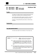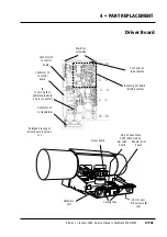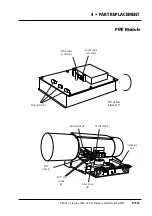
How to replace
Removal
1
• Remove the following covers:
Lamp cover
A
and back cover
B
, (section 4•2 steps 1-2).
2
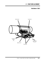
• Remove the two 2.5 mm countersunk screws
A
on each side of the
hardware unit and carefully slide the unit partially out.
3
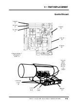
• Using a special PLCC removal tool, (fig. 2), remove the SCSI control-
ler from IC20 on the CPU module.
Note:
only use the special PLCC removal tool.
Do not
use other
tools, otherwise the chip socket will be damaged.
Assembly
4
• Fit a new SCSI controller into IC20 on the CPU board.
5
• Carefully push the hardware unit fully in, (connector J1 on the driver
board mates with the backplane) and fit the two 2.5 mm counter-
sunk allen screws
A
on each side of the unit.
6
• If no further replacement operations are required refit the covers
removed in step 1 in accordance with section 4•2.
Adjustments and tests required
No adjustments are required
Service Manual • ScanMate 4000/5000 Edition 1
•
January 1996
SCSI Controller
4•8b
Содержание ScanMate 4000
Страница 1: ...ScanMate 5000 ScanMate 4000 ...
Страница 6: ......
Страница 16: ......
Страница 18: ......
Страница 20: ......
Страница 22: ......
Страница 24: ......
Страница 28: ......
Страница 40: ......
Страница 44: ......
Страница 48: ......
Страница 52: ......
Страница 56: ......
Страница 60: ......
Страница 64: ......
Страница 68: ......
Страница 72: ......
Страница 76: ......
Страница 80: ......
Страница 84: ......
Страница 88: ......
Страница 92: ......
Страница 96: ......
Страница 100: ......
Страница 102: ......
Страница 106: ......
Страница 110: ......
Страница 113: ...5 ADJUSTMENTS AND TESTING Focus Calibration Edition 1 January 1996 Service Manual ScanMate 4000 5000 5 4c ...
Страница 114: ......
Страница 118: ......
Страница 122: ......
Страница 126: ......
Страница 130: ......
Страница 134: ......
Страница 138: ......
Страница 142: ......
Страница 146: ......
Страница 149: ...5 ADJUSTMENTS AND TESTING Stripes in Shadow Edition 1 January 1996 Service Manual ScanMate 4000 5000 5 13c Fig 1 Fig 2 ...
Страница 150: ......
Страница 153: ...5 ADJUSTMENTS AND TESTING Noise in Highlight Edition 1 January 1996 Service Manual ScanMate 4000 5000 5 14c Fig 1 ...
Страница 154: ......
Страница 156: ......
Страница 162: ......
Страница 164: ......
Страница 168: ...Service Manual ScanMate 4000 5000 Edition 1 January 1996 CPU Board 7 6 7 DIAGRAMS AND LAYOUTS SCSI controller ...
Страница 170: ......
Страница 171: ...ScanMate 4000 Type 250 Circuit Connection Diagram ...
Страница 172: ...ScanMate 5000 Type 210 Circuit Connection Diagram ...
Страница 174: ......


