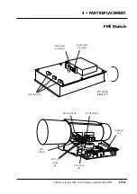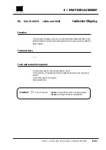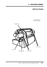
How to replace
Removal
1
• Remove the following covers:
Lamp cover
A
and back cover
B
, (section 4•2 steps 1-2).
2
• Remove the hardware unit, (section 4•5, steps 2-6).
3
• Disconnect connector J20, (green)
or
J21, (black) from the control board.
Note:
earlier model scanners use J20, (green)- see the note in step 11.
4
• Loosen the three 3 mm set screws
A
on the sensor module, securing
the three RGB fibre optics cables, and carefully remove the cables.
Note:
mark the cables as necessary to ensure correct refitment.
5
• Loosen the 3 mm allen screw
B
securing the PMT module to its tray
and slide the module out.
Assembly
6
• Fit the three fibre optics cables (as marked in step 4) into the sensor
module and tighten the 3 mm set screws
A
.
Note
: Do not bend the fibre optics cable excessively when fitting.
7
• Connect connector J20, (green)
or
J21, (black) to the control board.
Note:
If J20, (green) is used, it is possible to fit it both ways. If fitted in-
correctly, it will cause the amplifiers in the PMT module to blow. Ensure
that the locking tabs on the connector fit into the locks on the control
board, (that is, facing to the
right hand side
viewed from the
back
of the
scanner).
8
• Carry out a PMT amplifier gain adjustment, (section 5•6).
9
• Fit the new PMT module by positioning the board onto its tray and
carefully pushing in.
10
• Tighten the 3 mm allen screw
B
.
11
• Partially refit the hardware unit, (section 4•5 steps 7-10).
Note:
if J20 (green) is used on the control board, ensure that is con-
nected correctly, (see the caution on the previous page, 4•11a).
12
• Carry out the adjustment and test operations specified below, (except
PMT amplifier gain as this was carried out in step 8).
13
• Carefully push the hardware unit fully in, (connector J1 on the driver
board mates with the backplane) and fit the two 2.5 mm countersunk
allen screws
A
on each side of the unit.
14
• If no further replacement operations are required, refit the covers
removed i n step 1 in accordance with section 4•2.
Adjustments required
PMT amplifier gain adjustment, (section 5•6).
White calibration in transmission and reflection (section 5•5).
Register error (section 5•12) and stripes in shadow (section 5•13).
Service Manual • ScanMate 4000/5000 Edition 1
•
January 1996
PMT Module
4•11b
Содержание ScanMate 4000
Страница 1: ...ScanMate 5000 ScanMate 4000 ...
Страница 6: ......
Страница 16: ......
Страница 18: ......
Страница 20: ......
Страница 22: ......
Страница 24: ......
Страница 28: ......
Страница 40: ......
Страница 44: ......
Страница 48: ......
Страница 52: ......
Страница 56: ......
Страница 60: ......
Страница 64: ......
Страница 68: ......
Страница 72: ......
Страница 76: ......
Страница 80: ......
Страница 84: ......
Страница 88: ......
Страница 92: ......
Страница 96: ......
Страница 100: ......
Страница 102: ......
Страница 106: ......
Страница 110: ......
Страница 113: ...5 ADJUSTMENTS AND TESTING Focus Calibration Edition 1 January 1996 Service Manual ScanMate 4000 5000 5 4c ...
Страница 114: ......
Страница 118: ......
Страница 122: ......
Страница 126: ......
Страница 130: ......
Страница 134: ......
Страница 138: ......
Страница 142: ......
Страница 146: ......
Страница 149: ...5 ADJUSTMENTS AND TESTING Stripes in Shadow Edition 1 January 1996 Service Manual ScanMate 4000 5000 5 13c Fig 1 Fig 2 ...
Страница 150: ......
Страница 153: ...5 ADJUSTMENTS AND TESTING Noise in Highlight Edition 1 January 1996 Service Manual ScanMate 4000 5000 5 14c Fig 1 ...
Страница 154: ......
Страница 156: ......
Страница 162: ......
Страница 164: ......
Страница 168: ...Service Manual ScanMate 4000 5000 Edition 1 January 1996 CPU Board 7 6 7 DIAGRAMS AND LAYOUTS SCSI controller ...
Страница 170: ......
Страница 171: ...ScanMate 4000 Type 250 Circuit Connection Diagram ...
Страница 172: ...ScanMate 5000 Type 210 Circuit Connection Diagram ...
Страница 174: ......


