


Function
The control board differs between the ScanMate 4000 and 5000, (both
0200 and 0210 models), but removal and assembly is identical.
It contains control circuits for the DC motor, spindle step motor, sam-
ple control, color look-up table, A/D converter and holds the SCSI and
RS 232 PC interfaces, CPU, memory and firmware.
Technical data
-----
Tools and materials required
2 mm allen key for back cover and hardware unit mounting screws
Posidrive screwdriver
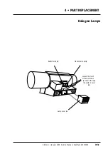
4 • PART REPLACEMENT
PN
960 25 000 10
(4000)
Control Board
PN
960 20 000 10
(5000 - 0200 model)
PN
960 21 000 10
(5000 - 0210 model)
Edition 1
•
January 1996 Service Manual • ScanMate 4000/5000
4•6a
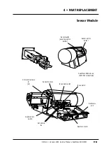
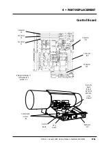
Caution!
☛
Turn off power
• Before
connecting or disconnecting cables.
• Before
carrying out service operations.
☛
If a green colored connector is used in connection J20 on the
control board, ensure that is reconnected with the locking tabs
on the
right hand side
, viewed from the
back
of the scanner. If
reconnected incorrectly, the amplifiers in the PMT module will
blow.
Содержание ScanMate 4000
Страница 1: ...ScanMate 5000 ScanMate 4000 ...
Страница 6: ......
Страница 16: ......
Страница 18: ......
Страница 20: ......
Страница 22: ......
Страница 24: ......
Страница 28: ......
Страница 40: ......
Страница 44: ......
Страница 48: ......
Страница 52: ......
Страница 56: ......
Страница 60: ......
Страница 64: ......
Страница 68: ......
Страница 72: ......
Страница 76: ......
Страница 80: ......
Страница 84: ......
Страница 88: ......
Страница 92: ......
Страница 96: ......
Страница 100: ......
Страница 102: ......
Страница 106: ......
Страница 110: ......
Страница 113: ...5 ADJUSTMENTS AND TESTING Focus Calibration Edition 1 January 1996 Service Manual ScanMate 4000 5000 5 4c ...
Страница 114: ......
Страница 118: ......
Страница 122: ......
Страница 126: ......
Страница 130: ......
Страница 134: ......
Страница 138: ......
Страница 142: ......
Страница 146: ......
Страница 149: ...5 ADJUSTMENTS AND TESTING Stripes in Shadow Edition 1 January 1996 Service Manual ScanMate 4000 5000 5 13c Fig 1 Fig 2 ...
Страница 150: ......
Страница 153: ...5 ADJUSTMENTS AND TESTING Noise in Highlight Edition 1 January 1996 Service Manual ScanMate 4000 5000 5 14c Fig 1 ...
Страница 154: ......
Страница 156: ......
Страница 162: ......
Страница 164: ......
Страница 168: ...Service Manual ScanMate 4000 5000 Edition 1 January 1996 CPU Board 7 6 7 DIAGRAMS AND LAYOUTS SCSI controller ...
Страница 170: ......
Страница 171: ...ScanMate 4000 Type 250 Circuit Connection Diagram ...
Страница 172: ...ScanMate 5000 Type 210 Circuit Connection Diagram ...
Страница 174: ......


