


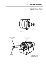


How to replace
Removal
1
• Remove the left hand end plate
E
and left hand drum cover
F
, (section 4•2).
2
• Turn on power and access the service program, (section 3•5).
3
• Select
1
, (
Move spindle
) and
L
, (
Set drum to lock position
).
4
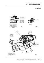
• Remove the two 2.5 mm dome-headed allen screws
A
from the motor outer
cover and pull the cover away to the left, as viewed from the front of the scanner.
Note:
earlier model scanners were retained by two studs instead of allen screws.
With this version, pull the cover to the left, away from the studs.
5
• Select
Z
, (
Set drum to zero position
) and turn off power.
6
• Remove the two allen screws
B
from the motor inner cover and remove the cover.
7
• Disconnect the DC motor and encoder connectors from the connector PCB and
remove the tape securing the leads to the motor.
8
• Remove the tape over the access hole to the shaft attachment set screws
C
.
9
• Manually rotate the drum until one of the two 4 mm set screws
C
retaining the
motor shaft to the drum is accessible.
10
• Remove and discard the set screw, rotate the drum 180
°
and remove and discard
the second 4 mm set screw.
11
• Remove the two 4 mm allen screws
D
attaching the motor to the drum sleeve and
remove the motor.
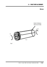
Assembly
Note:
rotate the motor shaft so that one of the flat faces will be visible in the access
hole when the motor is fitted.
12
• Loosen the three 4 mm allen screws
E
securing the outer sleeve of the new motor,
mount the motor and push it firmly against the drum sleeve.
13
• Check that the flat face on the motor shaft is positioned correctly in the access
hole and using loctite 243, fit a
new
set screw
C
.
14
• Rotate the drum 180
°
and using loctite 243, fit the second
new
4 mm set screw
C
.
15
• Push the outer sleeve of the motor up against the drum sleeve, tighten the three
4 mm allen screws
E,
fit the two 4 mm allen screws
D
and seal the hole with tape.
16
• Reconnect the motor and encoder connectors to the connector PCB and position
the jumper as per the note below. Secure the leads to the motor with tape.
Note:
for ScanMate 5000 (0200 and 0210 models), if the green connector is used,
connect the jumper to the upper position on the board. If the black connector is
used, connect the jumper to the lower position, (fig. 1).
17
• Carry out a zero point vertical, (section 5•8).
18
• Carry out a white calibration in transmission and reflection, (section 5•5) and regi-
ster error, (section 5•12).
19
• Refit the motor inner panel using the two allen screws
B
and mount the motor
outer panel ensuring that the stud on the inside of the panel locates in the elongat-
ed hole of the inner panel.
Note:
for earlier model scanners, push in to the right to lock the two studs in the
end of the panel. For later model scanners, refit the two allen screws
A
.
20
• Refit the covers removed in step 1 in accordance with section 4•2.
Service Manual • ScanMate 4000/5000 Edition 1
•
January 1996
DC Motor
4•15b
Содержание ScanMate 4000
Страница 1: ...ScanMate 5000 ScanMate 4000 ...
Страница 6: ......
Страница 16: ......
Страница 18: ......
Страница 20: ......
Страница 22: ......
Страница 24: ......
Страница 28: ......
Страница 40: ......
Страница 44: ......
Страница 48: ......
Страница 52: ......
Страница 56: ......
Страница 60: ......
Страница 64: ......
Страница 68: ......
Страница 72: ......
Страница 76: ......
Страница 80: ......
Страница 84: ......
Страница 88: ......
Страница 92: ......
Страница 96: ......
Страница 100: ......
Страница 102: ......
Страница 106: ......
Страница 110: ......
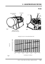
Страница 113: ...5 ADJUSTMENTS AND TESTING Focus Calibration Edition 1 January 1996 Service Manual ScanMate 4000 5000 5 4c ...
Страница 114: ......
Страница 118: ......
Страница 122: ......
Страница 126: ......
Страница 130: ......
Страница 134: ......
Страница 138: ......
Страница 142: ......
Страница 146: ......
Страница 149: ...5 ADJUSTMENTS AND TESTING Stripes in Shadow Edition 1 January 1996 Service Manual ScanMate 4000 5000 5 13c Fig 1 Fig 2 ...
Страница 150: ......
Страница 153: ...5 ADJUSTMENTS AND TESTING Noise in Highlight Edition 1 January 1996 Service Manual ScanMate 4000 5000 5 14c Fig 1 ...
Страница 154: ......
Страница 156: ......
Страница 162: ......
Страница 164: ......
Страница 168: ...Service Manual ScanMate 4000 5000 Edition 1 January 1996 CPU Board 7 6 7 DIAGRAMS AND LAYOUTS SCSI controller ...
Страница 170: ......
Страница 171: ...ScanMate 4000 Type 250 Circuit Connection Diagram ...
Страница 172: ...ScanMate 5000 Type 210 Circuit Connection Diagram ...
Страница 174: ......


