


How to adjust
1
• If access is not already available, remove the back cover
B
, (section 4•2
step 2).
2
• Remove the two 2.5 mm countersunk screws from each side of the hard-
ware unit and carefully slide the unit partially out.
3
• Insert the back plane extender onto connector J1 on the driver board and
carefully push the hardware unit back in.
4
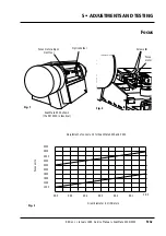
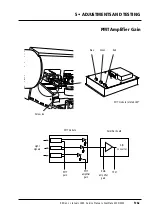
• Loosen the 3 mm allen screw
A
securing the PMT module to its tray,
slide the module out and rest it in a suitable position so that the three
potentiometers can be adjusted, (step 13).
5
• Fit a terminator to a SCSI connector on the scanner and SCSI cable and
RS 232 service cable to the scanner and PC.
6
• Set the Dip switch to 8, (on).
7
• Cover the side of the heat sink on the driver board, (see the “caution” on
the previous page).
8
• Turn on the PC or Mac and scanner and access the service program
main menu (section 3•5).
9
• Connect a voltmeter to TP 46 on the control board and record the
measurement.
10
• Turn all three potentiometers
A
(fig. 2) counter-clockwise to maximum.
11
• Select
1
, (
Move drum Z/P/L/.
) and then
.
, (“dot” - allows setting your
own drum position parameters) and move the empty drum over the
sensor. Finally select
q
, (
utility end
).
12
• Select
0
, (
Toggle lamps
) to turn on the transmission lamp.
13
• Select
2
, (
Adjust PMT gain
) and then press 2 and adjust the gain value
until the lowest voltage measured on TP46, TP47 and TP48 on the con-
trol board is 3.0
+
/
-
0.1 volt.
14
• Adjust the three potentiometers and measure the value on TP46, TP47
and TP48 until they are within 10% of each other and between 2.7 to
3.3 volts.
15
• Select
q
, (
done
) when complete.
16
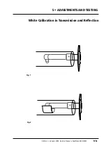
• Carry out a white calibration in transmission and reflection (section
5•5).
17
• Refit the PMT module and tighten the securing screw
A
.
18
• Remove the voltmeter and the cover over the driver board heat sink.
19
• Remove the driver board extender, carefully push the hardware unit fully
in, (connector J1 on the driver board mates with the backplane) and fit
the two 2.5 mm countersunk allen screws on each side of the unit.
20
• If no further adjustment or replacement operations are required,
remove the voltmeter and refit the back cover
B
accordance with sect-
ion 4•2.
Service Manual • ScanMate 4000/5000 Edition 1
•
January 1996
PMT Amplifier Gain
5•6b
Содержание ScanMate 4000
Страница 1: ...ScanMate 5000 ScanMate 4000 ...
Страница 6: ......
Страница 16: ......
Страница 18: ......
Страница 20: ......
Страница 22: ......
Страница 24: ......
Страница 28: ......
Страница 40: ......
Страница 44: ......
Страница 48: ......
Страница 52: ......
Страница 56: ......
Страница 60: ......
Страница 64: ......
Страница 68: ......
Страница 72: ......
Страница 76: ......
Страница 80: ......
Страница 84: ......
Страница 88: ......
Страница 92: ......
Страница 96: ......
Страница 100: ......
Страница 102: ......
Страница 106: ......
Страница 110: ......
Страница 113: ...5 ADJUSTMENTS AND TESTING Focus Calibration Edition 1 January 1996 Service Manual ScanMate 4000 5000 5 4c ...
Страница 114: ......
Страница 118: ......
Страница 122: ......
Страница 126: ......
Страница 130: ......
Страница 134: ......
Страница 138: ......
Страница 142: ......
Страница 146: ......
Страница 149: ...5 ADJUSTMENTS AND TESTING Stripes in Shadow Edition 1 January 1996 Service Manual ScanMate 4000 5000 5 13c Fig 1 Fig 2 ...
Страница 150: ......
Страница 153: ...5 ADJUSTMENTS AND TESTING Noise in Highlight Edition 1 January 1996 Service Manual ScanMate 4000 5000 5 14c Fig 1 ...
Страница 154: ......
Страница 156: ......
Страница 162: ......
Страница 164: ......
Страница 168: ...Service Manual ScanMate 4000 5000 Edition 1 January 1996 CPU Board 7 6 7 DIAGRAMS AND LAYOUTS SCSI controller ...
Страница 170: ......
Страница 171: ...ScanMate 4000 Type 250 Circuit Connection Diagram ...
Страница 172: ...ScanMate 5000 Type 210 Circuit Connection Diagram ...
Страница 174: ......


