


How to test
1
• Fit a terminator to a SCSI connector on the scanner and SCSI cable
and RS 232 service cable to the scanner and PC or Mac.
2
• Set theDip switch to 8, (on).
3
• Turn on the PC or Mac and access the service program main menu
(section 3•5).
4
• Switch on the scanner and start up Photoshop plug-in.
5
• Carry out a white calibration in transmission (section 5•5).
6
• Clean the drum with an anti-static cloth.
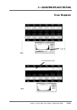
7
• Mount the ScanView focus adjust target firmly on the zero point of
the drum, (the junction of the vertical and horizontal lines) so that
the first of the thin black lines on the target is on the horizontal
line of the drum (fig. 1). Ensure also that the target lines are horiz-
ontal with the horizontal line on the drum.
8
• Select the following settings in Photoshop plug-in:
Transmission gray scale
Gamma 1.4
Neutral gradation curve
Max resolution
9
• Select the standard area 24 x 36 mm and make a preview.
10
• Crop an area of 20 x 15 mm that starts approximately 5 mm from
the first black line so that three black stripes can be seen (Fig. 2).
11
• Perform a scan and crop an area,
A
, as shown in fig. 2.
Note:
the area should be approximately 1000 pixels on the y-axis
and 10-20 pixels on the x-axis.
12
• Select
image
,
effects
and then
scale
.
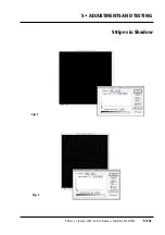
13
• Enlarge the area on the x-axis by a factor of 10 (fig. 3).
14
• Select
threshold
and make a threshold on the enlarged area (fig. 4).
15
• Choose what appears to be the worst area of irregularities in fig. 4.
16
• Zoom in 4:1 and make a crop of the area chosen.
17
• Choose the largest irregularity, select
show info.
and read the
W
value in the window (fig. 5).
18
• Divide this value by 10. The variation should be less than 1 pixel.
19
• If the variation is over 1.5 pixel, contact ScanView’s support
department.
Service Manual • ScanMate 4000/5000 Edition 1
•
January 1996
Register Error
5•12b
Содержание ScanMate 4000
Страница 1: ...ScanMate 5000 ScanMate 4000 ...
Страница 6: ......
Страница 16: ......
Страница 18: ......
Страница 20: ......
Страница 22: ......
Страница 24: ......
Страница 28: ......
Страница 40: ......
Страница 44: ......
Страница 48: ......
Страница 52: ......
Страница 56: ......
Страница 60: ......
Страница 64: ......
Страница 68: ......
Страница 72: ......
Страница 76: ......
Страница 80: ......
Страница 84: ......
Страница 88: ......
Страница 92: ......
Страница 96: ......
Страница 100: ......
Страница 102: ......
Страница 106: ......
Страница 110: ......
Страница 113: ...5 ADJUSTMENTS AND TESTING Focus Calibration Edition 1 January 1996 Service Manual ScanMate 4000 5000 5 4c ...
Страница 114: ......
Страница 118: ......
Страница 122: ......
Страница 126: ......
Страница 130: ......
Страница 134: ......
Страница 138: ......
Страница 142: ......
Страница 146: ......
Страница 149: ...5 ADJUSTMENTS AND TESTING Stripes in Shadow Edition 1 January 1996 Service Manual ScanMate 4000 5000 5 13c Fig 1 Fig 2 ...
Страница 150: ......
Страница 153: ...5 ADJUSTMENTS AND TESTING Noise in Highlight Edition 1 January 1996 Service Manual ScanMate 4000 5000 5 14c Fig 1 ...
Страница 154: ......
Страница 156: ......
Страница 162: ......
Страница 164: ......
Страница 168: ...Service Manual ScanMate 4000 5000 Edition 1 January 1996 CPU Board 7 6 7 DIAGRAMS AND LAYOUTS SCSI controller ...
Страница 170: ......
Страница 171: ...ScanMate 4000 Type 250 Circuit Connection Diagram ...
Страница 172: ...ScanMate 5000 Type 210 Circuit Connection Diagram ...
Страница 174: ......


