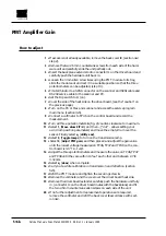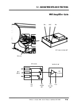
How to adjust
1
• If access is not already available, remove the lamp cover
A
, back cover
B
, right
hand end plate
C
and right hand drum cover
D
, (section 4•2 steps 1-4).
2
• Remove the two 2.5 mm countersunk screws from each side of the hardware
unit and carefully slide the unit partially out.
3
• Insert the back plane extender onto connector J1 on the driver board and
push the hardware unit back in.
4
• Fit a terminator to a SCSI connector on the scanner and SCSI cable and RS232
service cable to the scanner and PC.
5
• Set the Dip switch to 8, (on).
6
• Cover the side of the heat sink on the driver board, (see the “caution” on the
previous page).
7
• Turn on the PC or Mac and scanner and access the service program main
menu, (section 3•5).
8
• Select
1
, (
Move drum Z/P/L/.
), then
Z
, (
drum to zero position
) to move the drum
to the zero position.
9
• Select
1
again and then
.
, (“dot” allows setting your own drum position para-
meters) and position the drum about 1 cm to the left to ensure that the sensor
does not see the horizontal zero line. Select
q
, (
utility end
).
10
• Connect the oscilloscope signal probes to TP46, (use channel 1 as trigger) and
TP57, (channel 2) on the control board.
11
• Select
4
, (
Choose aperture
) and choose aperture number 1.
12
• Select
0
, (
Toggle lamps
) to turn on the transmission lamp.
13
• Set the oscilloscope to 2V/div. and 10 mS/div. and trigger on the negative edge
on the channel which is coupled to the analog signal (black line on the drum).
This gives an overview of the encoder signal position in relation to the zero line.
14
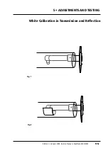
• The pulse on the oscilloscope could as an example appear as shown in fig. 1,
(the encoder and amplifier pulses show one revolution of the drum).
15
• If the pulse does not appear on channel 1, select
2
, (
Adjust PMT gain
) and
adjust the gain value until approximately 3 V is measured on TP 46. Select
q
,
(
done
) when complete.
16
• Remove the two DC motor covers, (section 4•15, steps 4 and 6). Loosen the
two 3 mm allen screws
A
securing the motor to the drum sleeve (fig. 4),
enough to allow adjustment of the motor.
17
• Gently rotate the motor until the two pulses on the oscilloscope are as shown
in fig. 2. This is a rough adjustment and gives a base for the fine adjustment in
step 18 below.
18
• Set the oscilloscope to 10
µ
S/div. and fine tune the adjustment until the encod-
er pulse is within the band of the amplifier pulse as shown in fig. 3.
19
• Tighten the two 3mm allen screws
A
firmly but not overtight, to secure the
motor and fit the two covers, (section 4•15, step 19).
20
• Remove the oscilloscope and the cover over the driver board heat sink.
21
• Remove the driver board extender, carefully push the hardware unit fully in,
(connector J1 on the driver board mates with the backplane) and fit the two
2.5 mm countersunk allen screws on each side of the unit.
22
• Refit the covers removed in step 1 in accordance with section 4•2.
Service Manual • ScanMate 4000/5000 Edition 1
•
January 1996
Zero Point Vertical
5•8b
Содержание ScanMate 4000
Страница 1: ...ScanMate 5000 ScanMate 4000 ...
Страница 6: ......
Страница 16: ......
Страница 18: ......
Страница 20: ......
Страница 22: ......
Страница 24: ......
Страница 28: ......
Страница 40: ......
Страница 44: ......
Страница 48: ......
Страница 52: ......
Страница 56: ......
Страница 60: ......
Страница 64: ......
Страница 68: ......
Страница 72: ......
Страница 76: ......
Страница 80: ......
Страница 84: ......
Страница 88: ......
Страница 92: ......
Страница 96: ......
Страница 100: ......
Страница 102: ......
Страница 106: ......
Страница 110: ......
Страница 113: ...5 ADJUSTMENTS AND TESTING Focus Calibration Edition 1 January 1996 Service Manual ScanMate 4000 5000 5 4c ...
Страница 114: ......
Страница 118: ......
Страница 122: ......
Страница 126: ......
Страница 130: ......
Страница 134: ......
Страница 138: ......
Страница 142: ......
Страница 146: ......
Страница 149: ...5 ADJUSTMENTS AND TESTING Stripes in Shadow Edition 1 January 1996 Service Manual ScanMate 4000 5000 5 13c Fig 1 Fig 2 ...
Страница 150: ......
Страница 153: ...5 ADJUSTMENTS AND TESTING Noise in Highlight Edition 1 January 1996 Service Manual ScanMate 4000 5000 5 14c Fig 1 ...
Страница 154: ......
Страница 156: ......
Страница 162: ......
Страница 164: ......
Страница 168: ...Service Manual ScanMate 4000 5000 Edition 1 January 1996 CPU Board 7 6 7 DIAGRAMS AND LAYOUTS SCSI controller ...
Страница 170: ......
Страница 171: ...ScanMate 4000 Type 250 Circuit Connection Diagram ...
Страница 172: ...ScanMate 5000 Type 210 Circuit Connection Diagram ...
Страница 174: ......


