Now to replace
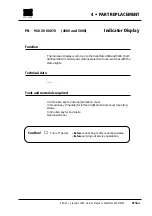
Removal
1
• Remove the following covers:
Right hand end plate
C
, right hand drum cover
D
, left hand end
plate
E
and left hand drum cover
F
, (section 4•2 steps 3 and 6).
2
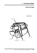
• Remove the four 3 mm allen screws
A
, (two each side of the drum),
securing the internal protection cover.
3
• Slide the cover to the right, (viewed from the front of the scanner),
in order to give access to the back of the indicator display.
4
• Carefully pull the display ribbon cable away from its adhesive pad
and disconnect the connector.
5
• Using a small screwdriver or other suitable tool, peel the indicator
display away from the scanner.
Assembly
6
• Clean the area on the cabinet where the new display is to be fitted,
with isopropyl alcohol.
7
• Peel the protective paper from the back of the new display, feed the
ribbon cable through the opening in the drum and firmly press the
display into place.
8
• Reconnect the connector and press the ribbon cable down onto
the adhesive pad.
9
• Position the internal protection cover and secure it with the four 3
mm allen screws
A
, (two each side of the drum).
10
• If no further replacement operations are required, refit the covers
removed in step 1 in accordance with section 4•2.
Adjustments required
No adjustments are necessary.
Service Manual • ScanMate 4000/5000 Edition 1
•
January 1996
Indicator Display
4•12b
Содержание ScanMate 4000
Страница 1: ...ScanMate 5000 ScanMate 4000 ...
Страница 6: ......
Страница 16: ......
Страница 18: ......
Страница 20: ......
Страница 22: ......
Страница 24: ......
Страница 28: ......
Страница 40: ......
Страница 44: ......
Страница 48: ......
Страница 52: ......
Страница 56: ......
Страница 60: ......
Страница 64: ......
Страница 68: ......
Страница 72: ......
Страница 76: ......
Страница 80: ......
Страница 84: ......
Страница 88: ......
Страница 92: ......
Страница 96: ......
Страница 100: ......
Страница 102: ......
Страница 106: ......
Страница 110: ......
Страница 113: ...5 ADJUSTMENTS AND TESTING Focus Calibration Edition 1 January 1996 Service Manual ScanMate 4000 5000 5 4c ...
Страница 114: ......
Страница 118: ......
Страница 122: ......
Страница 126: ......
Страница 130: ......
Страница 134: ......
Страница 138: ......
Страница 142: ......
Страница 146: ......
Страница 149: ...5 ADJUSTMENTS AND TESTING Stripes in Shadow Edition 1 January 1996 Service Manual ScanMate 4000 5000 5 13c Fig 1 Fig 2 ...
Страница 150: ......
Страница 153: ...5 ADJUSTMENTS AND TESTING Noise in Highlight Edition 1 January 1996 Service Manual ScanMate 4000 5000 5 14c Fig 1 ...
Страница 154: ......
Страница 156: ......
Страница 162: ......
Страница 164: ......
Страница 168: ...Service Manual ScanMate 4000 5000 Edition 1 January 1996 CPU Board 7 6 7 DIAGRAMS AND LAYOUTS SCSI controller ...
Страница 170: ......
Страница 171: ...ScanMate 4000 Type 250 Circuit Connection Diagram ...
Страница 172: ...ScanMate 5000 Type 210 Circuit Connection Diagram ...
Страница 174: ......


