


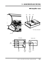


How to adjust
1
• If access is not already available, remove the lamp cover
A
, back cover
B
, right
hand end plate
C
and right hand drum cover
D
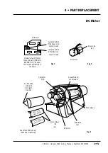
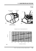
, (section 4•2 steps 1-4).
2
• Remove the two 2.5 mm countersunk screws from each side of the hardware
unit and carefully slide the unit partially out.
3
• Insert the back plane extender onto connector J1 on the driver board and care-
fully push the hardware unit back in.
4
• Fit a terminator to a SCSI connector on the scanner and SCSI cable and RS 232
service cable to the scanner and PC.
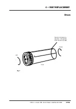
5
• Set the Dip switch to 8, (on).
6
• Cover the side of the heat sink on the driver board, (see the “caution” on the
previous page).
7
• Turn on the PC or Mac and scanner and start up Photoshop plug-in.
8
• Carry out a white calibration in transmission (section 5•5).
9
• Access the service program main menu (section 3•5).
10
• Lock the drum by pressing
Lock drum
on the indicator display.
11
• Remove the drum and mount the focus motor adjustment tool (fig. 1) onto the
drum platform.
Note: do not
rotate the drum platform while the adjustment tool is fitted.
12
• Remove the 3 mm set screw securing the optics holder to the sensor lens and
remove the holder (fig. 1).
13
• From the service program main menu, select
H
, (
Set focus to zero
).
14
• Loosen the two 3 mm allen screws
B
(fig. 2) securing the focus motor to the
sensor. The motor will now move to the rear under spring pressure.
15
• From the service program main menu, select
1
, (
Move drum Z/P/L/.
), then
.
,
(“dot” allows setting your own drum position parameters) and move the drum
spindle until the adjustment tool is directly in front of the sensor.
16
• Push the focus motor towards the drum tool until the sensor head and tool
touch. The tool should now rotate with light resistance from the sensor head.
17
• Maintain the pressure on the focus motor and tighten the two 3 mm allen
screws
B
on the focus motor. (Recheck the resistance on the adjustment tool
after tightening the screws).
18
• Select
1
, (
Move drum Z/P/L/.
), then
L
to move the drum back to the lock posit-
ion and remove the adjustment tool.
19
• Refit the optics holder and tighten the 3 mm set screw.
20
• Make a focus calibration from photoshop plug-in.
21
• Press
Alt
+
Option
in plug-in and read the step values
or * Show scanner opti-
ons
in the service program can be selected and focus values for drums 0-9 will
be shown, together with barcode reading information.
22
• Check that these values are within the tolerances of the graph (fig. 3) by read-
ing the diameter on the drum flange.
23
• Remove the cover over the driver board heat sink.
24
• Remove the driver board extender, push the hardware unit fully in and refit
the two 2.5 mm countersunkscrews on either side of the unit.
25
• Refit the covers removed in step 1 in accordance with section 4•2.
Service Manual • ScanMate 4000/5000 Edition 1
•
January 1996
Focus
5•3b
Содержание ScanMate 4000
Страница 1: ...ScanMate 5000 ScanMate 4000 ...
Страница 6: ......
Страница 16: ......
Страница 18: ......
Страница 20: ......
Страница 22: ......
Страница 24: ......
Страница 28: ......
Страница 40: ......
Страница 44: ......
Страница 48: ......
Страница 52: ......
Страница 56: ......
Страница 60: ......
Страница 64: ......
Страница 68: ......
Страница 72: ......
Страница 76: ......
Страница 80: ......
Страница 84: ......
Страница 88: ......
Страница 92: ......
Страница 96: ......
Страница 100: ......
Страница 102: ......
Страница 106: ......
Страница 110: ......
Страница 113: ...5 ADJUSTMENTS AND TESTING Focus Calibration Edition 1 January 1996 Service Manual ScanMate 4000 5000 5 4c ...
Страница 114: ......
Страница 118: ......
Страница 122: ......
Страница 126: ......
Страница 130: ......
Страница 134: ......
Страница 138: ......
Страница 142: ......
Страница 146: ......
Страница 149: ...5 ADJUSTMENTS AND TESTING Stripes in Shadow Edition 1 January 1996 Service Manual ScanMate 4000 5000 5 13c Fig 1 Fig 2 ...
Страница 150: ......
Страница 153: ...5 ADJUSTMENTS AND TESTING Noise in Highlight Edition 1 January 1996 Service Manual ScanMate 4000 5000 5 14c Fig 1 ...
Страница 154: ......
Страница 156: ......
Страница 162: ......
Страница 164: ......
Страница 168: ...Service Manual ScanMate 4000 5000 Edition 1 January 1996 CPU Board 7 6 7 DIAGRAMS AND LAYOUTS SCSI controller ...
Страница 170: ......
Страница 171: ...ScanMate 4000 Type 250 Circuit Connection Diagram ...
Страница 172: ...ScanMate 5000 Type 210 Circuit Connection Diagram ...
Страница 174: ......


