


RTC
®
5 PC Interface Board
Rev. 1.9 e
8 Advanced Functions for Scan Head and Laser Control
195
innovators for industry
The scanners thereby move with equal speed beyond
the actual end point. 10
µ
s clock cycles that are
begun will be executed to completion (particularly for
pixel frequencies > 100 kHz).
The
command switches off the
“laser active” laser control signals at the beginning of
an image line (a LaserOff delay will be waited for, if
necessary, before switching off – e.g. when a
preceding mark command is still being processed).
The “laser active” laser control signals will then be
switched on with the first
/
command, but delayed by a LaserOn Delay with
respect to the start of scanner motion. The pixel
pulses will be outputted possibly (in accordance with
the previously activated laser version and its set
values) delayed by an additional Pixel Delay (see
). The Pixel Delay is
• = 0 in CO
2
mode
• = 0 (or Q-Switch delay) in YAG mode 1
• = length of the FirstPulseKiller signal (or Q-Switch
delay) in YAG mode 2
• = 10
µ
s (or Q-Switch delay) in YAG mode 3
• = Q-Switch delay in YAG mode 5.
The analog signal (at the ANALOG OUT1 or
ANALOG OUT2 port) changes synchronously with the
leading edge of each pixel pulse (see
Note:
The DA converter requires about 1.5
µ
s … 3
µ
s to
produce a stable analog output signal. For pixel frequencies
above around 100 kHz (i.e. for a
HalfPeriod
< approx.
320) digital-to-analog conversion can’t always be fully
completed. For such pixel frequencies, the user must care-
fully verify that sufficient capability is available.
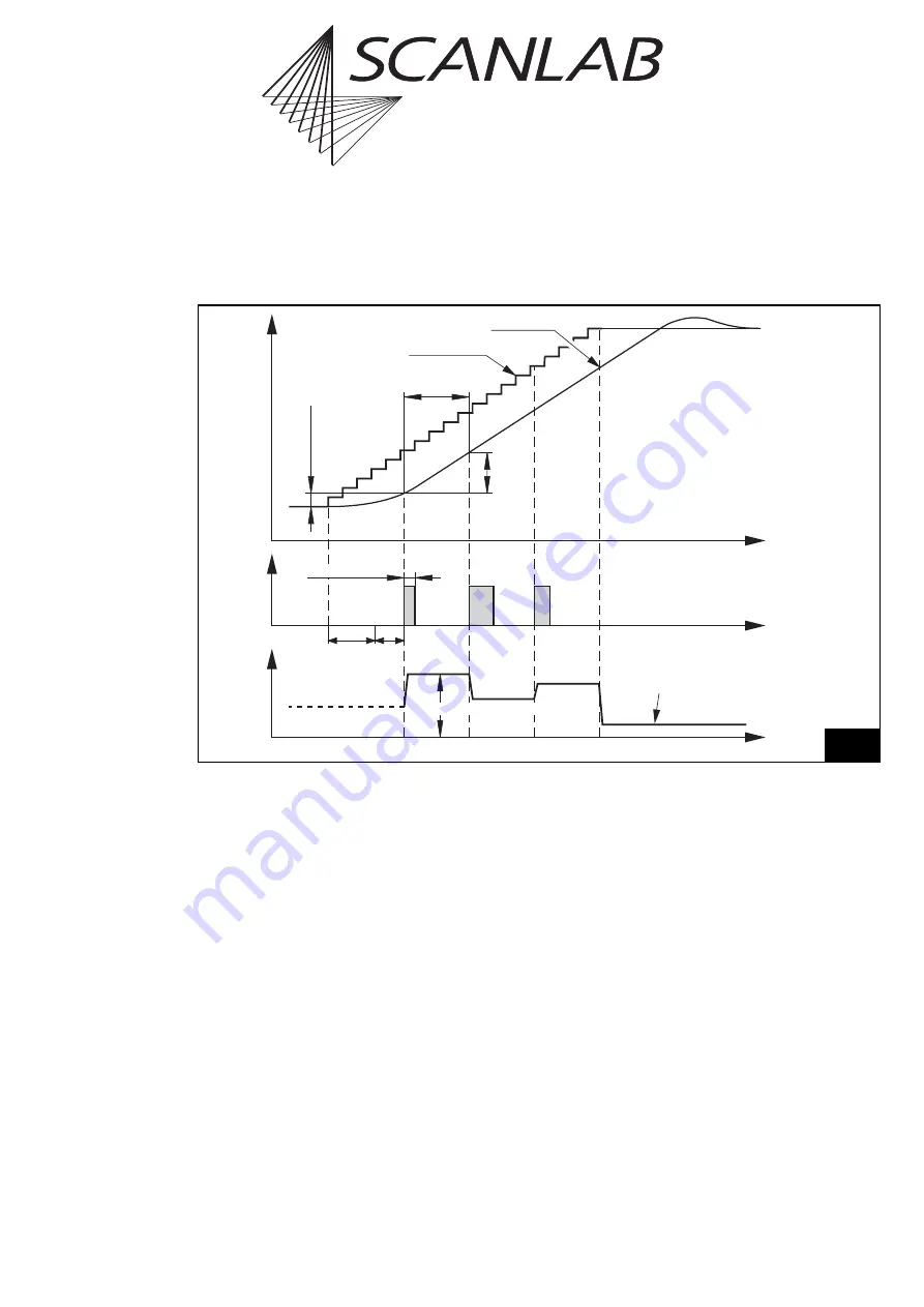
The pixel pulse delay or analog level change relative
to the scanner motion (i.e. the LaserOn delay and
pixel delay) should be set in such a way that the
galvanometer scanners’ acceleration phase (in which
the scanners are brought to a constant speed) is
masked. Alternatively, distortions during the acceler-
ation phase can be suppressed via inserting some idle
pixels (e.g. with zero pulse length) at the beginning
of each image line.
56
Timing of the scanner positions and the laser control signals in the pixel output mode.
The pixel output period in this example is approx. 4.5 microsteps.
PulseLength
= 0
Pixel 0
Pixel 1
Pixel 2
dX,dY
Scanner Position
Pixel Pulses
LaserOn
Delay
Time
Real Position
Set Position
(Microvectors)
Default Pixel
Pixel
Delay
AnalogOut
= 0xFFF
or according to
set_laser_off_default
AnalogOut
Pixel Values
Pixel Period
= 2 x
HalfPeriod
Analog Signal
Time
PulseLength
Time
Line Shift


