6
- 14
6
Maintenance Procedures
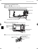
Cord cli
p
S
olenoid
valve
connector
(DRV1)
Clam
ps
Bindin
g
b
and
s
S
olenoid valve
S
olenoid
valve
in
s
tallation
b
racket A
S
olenoid valve in
s
tallation
b
racket A
Joint
Joint
S
crew
s
S
crew
s
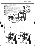
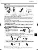
Replace the solenoid valve.
(1) Cut the binding bands (2) inside the electrical component box, then disconnect the solenoid valve
connector and remove the cord from the clamps (2).
6
(2) Remove the solenoid valve installation bracket A (2 screws), then disconnect the transparent tube from the
left joint. Lift up the solenoid valve unit while pulling it out toward the front. (For the method used to
disconnect the transparent tube from the joint, refer to step
from “Replacing the Virus Washer
element.”)
5
(3) Remove the solenoid valve from the installation bracket A (2 screws).
07-032 VW-VF10BG_TD 2/15/07 11:25 AM Page 14

