Maintenance Procedures
6
- 15
6
Control PCB
mountin
g
b
racket
Electrical com
p
onent
b
ox cover
Power PCB
Fan PCB
S
crew
s
S
crew
s
(4)
S
crew
s
(2)
S
crew
s
(2)
Electroly
s
i
s
Condition
S
ettin
g
PCB
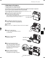
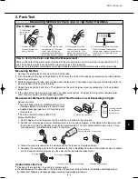
11. Replacing the PCBs inside the electrical component box
Stop the system and unplug the power cord.
Remove the top and bottom parts of the front panel.
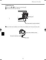
Remove the electrical component box cover (4 screws). Disconnect all cords that run into the electrical
component box. Next, remove the screws (2 each on the left and right sides) that fasten the electrical
component box and remove the electrical component box.
3
2
1
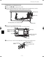
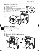
The PCBs are arranged as shown in the figure below. When removing the power PCB or fan PCB,
first remove the control PCB mounting bracket (4 screws) then remove the power PCB or fan PCB.
4
07-032 VW-VF10BG_TD 2/15/07 11:25 AM Page 15


