5
- 7
5
PCB and Functions
4. Changing the Cleaning Monitor Display
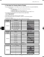
The cleaning monitor display can be changed by means of setting item code “88” on the control PCB EEPROM.
Setting data
00: Standard display (setting at time of shipment from the factory)
01: Humidity indicator
02: Blinking line display when cleaning indicator is full
03: Blinking line display when humidity indicator and cleaning indicator are full
Use the maintenance remote control unit to change the cleaning monitor display.
(1) RCS-TM80BG (85978487)
(2) Wire K (8540528057900)
This operation must be performed when the system is stopped.
For the <Preparation for change> and <Procedure>, refer to “3. Turning the Buzzer ON/OFF.”
<Cleaning monitor display>
(1) Setting data 00: Standard display (setting at time of shipment from the factory)
Unit status
Total airflow
TREATED AIR VOLUME
Stopped
0 – Less than 300 m
3
300 – Less than 600 m
3
Operating
600 – Less than 900 m
3
900 – Less than 1200 m
3
1200 – Less than 1500 m
3
1500 m
3
or more
(2) Setting data 01: Humidity indicator (Displayed when the FILTER RESET SW is pressed.)
Unit status
Humidity
TREATED AIR VOLUME
Stopped
29 % or less
(Blinking)
30 – 39 %
40 – 49 %
Operating
50 – 59 %
60 – 69 %
70 – 79 %
80 % or more
(Blinking)
(3) Setting data 02: Blinking line display when cleaning indicator is full
Unit status
1
→
6
→
1 (Repeats)
TREATED AIR VOLUME
1
2
Operating
3
4
5
6
(4) Setting data 03: Blinking line display when humidity indicator and cleaning indicator are full.
07-032 VW-VF10BG_TD 2/15/07 11:25 AM Page 8


