7
Installation
Test Run
I
Test run
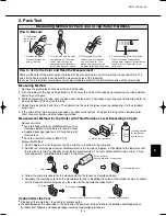
1. Be sure to set the electrolysis condition. (Refer to the Instruction Manual.)
2. Fill the water tank all the way with tap water.
G
Be sure to use normal tap (drinking) water.
Never use water from a water purifier, water from a water heater, alkali ion water, mineral water, well water,
seawater, or similar types of water.
These types of water cannot be electrolyzed and can cause the growth of mold or bacteria, resulting in odor.
G
The electrolysis condition setting must be set correctly according to the water quality in the region
where the product is used.
For details, refer to Section 2. USING THIS SYSTEM of the Instruction Manual.
G
Verify that the electrolysis condition setting switch is in the correct position.
Water tank
p
anel
Water tank
Fill with water
to thi
s
p
oint.
Ca
p
9. Because the automatic cleaning operation function keeps the inside of the system clean when the system is
stopped, do not unplug the power cord after the test run, and verify that there is sufficient water in the water tank.
* After installation, if the system will not be used for a long period of time, drain the water from the water tank and
electrolyzed water tray, and fully dry the Virus Washer element.
(For details, refer to the Instruction Manual.)
3. Tighten the cap. At this time, check that no water spills
from the water tank.
4. Place the water tank in the designated position
in the unit.
5. Insert the tank gently.
6. Press the control panel ON/OFF button.
7. Verify that this product begins operating correctly.
At this time, verify that there is no abnormal noise
from the unit, and that there is no vibrating noise.
Control
s
ection
p
anel
FILTER lam
p
(red)
CHECK lam
p
(red)
DRAIN lam
p
(red)
ADD WATER lam
p
(red)
OPERATION lam
p
(
g
reen)
HUMIDITY
S
AVER lam
p
(
g
reen)
FAN
S
PEED
b
utton
Pre
ss
thi
s
b
u
tto
n
to
cha
ng
e the fa
n
s
peed.
CHILD LOCK lam
p
CHILD LOCK
b
utton
DRAIN/DRY lam
p
DRAIN/DRY
b
utton
FILTER RE
S
ET
b
utton
LOUVER
b
utton
O
p
eratin
g
mode
I
n
dicate
s
the fa
n
s
peed.
ON/OFF
b
utton
: ON
: Blinking (1 second ON, 1 second OFF)
2: Blinking (2 seconds ON, 1 second OFF)
G
: OFF
Unit built-in control section
Unit front display
Control section
Display
Operation status
CHECK
FILTER
DRAIN
ADD WATER HUMIDITY SAVER OPERATION CHILD LOCK DRAIN/DRY
LED
LED
LED
LED
LED
LED
LED
LED
Stopped
G
G
G
G
G
G
G
G
Operating
G
G
G
G
G
G
G
Alarm
G
G
G
G
G
G
Filter indicator
G
G
G
G
G
G
Add water request
G
G
G
G
G
G
Drain request
G
G
G
G
G
G
Freeze prevention activated
G
G
G
G
G
G
Warming up
G
G
G
G
G
2
G
G
Drainage control in progress
G
G
G
G
G
G
G
Child lock engaged
G
G
G
G
G
G
G
8. LED indications
The meaning of the LED indications on the unit front display are as shown below. Take appropriate steps
according to the system status.
7
- 5
07-032 VW-VF10BG_TD 2/15/07 11:25 AM Page 6


