Using this System
2
- 2
2
1. Before Using this System
5
5
0
4
9
3
8
2
7
1
6
Electroly
s
i
s
co
n
ditio
n
s
etti
ng
s
witch
Kno
b
Pen or
s
imilar item
Mi
n
im
u
m 100 cm
Mi
n
im
u
m
10 cm
Mi
n
im
u
m 100 cm
Mi
n
im
u
m
10 cm
1ø AC 220 – 240 V
2-pi
n
pl
ug
with
g
ro
un
di
ng
s
ocket
Checking the installation location
Do not install the system in the following locations:
G
Near curtains, or on carpets
These items can obstruct the intake and outlet, and can
cause system malfunction.
G
High locations, inclined locations, or unstable
locations
Human contact may cause the unit to fall or tip over. If the
unit is installed in an inclined location, the water level
sensor may be activated, causing the ADD WATER lamp to
light, stopping operation, and resulting in water leakage.
Be sure to connect the electrical ground wire.
CAUTION
Ensure the space around the unit that is shown
in the figure below.
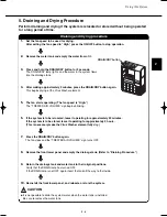
1.
Press at the points marked “PUSH” on both sides at the top of the front upper panel, then pull the top
of the panel toward you to remove it.
2.
It is necessary to set the optimal electrolysis condition for the tap water to be used by the Virus Washer
system. For this purpose, the dealer determines the chlorine ion concentration and the hardness of the
tap water, and sets the electrolysis condition according to the figure below.
Tap water with hardness of 400 ppm or more cannot be used because this level of hardness is too high.
CAUTION
1. Setting the electrolysis condition (set by the dealer)
G
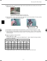
In regions where the electrolysis condition is 7, turn the
electrolysis condition switch knob to “7” and add salt (1 g)
to the water tank. (Refer to “Adding salt.”)
(A pen or similar item is useful for turning the knob.)
(At the time of shipment, this knob is set to “5.”)
G
When removing the front upper panel, take care not to drop it, and be careful
when setting it on the floor.
*1: In regions where the chlorine ion concentration is 5 ppm or less, add salt
to the water tank and use setting No. 7.
*2: Set the electrolysis condition according to the tap water that is used.
No. 6
No. 5
Tap water chlori
n
e
io
n
co
n
ce
n
tratio
n
Electroly
s
i
s
co
n
ditio
n
No. 4
No.
3
Tap water chlori
n
e
io
n
co
n
ce
n
tratio
n
Electroly
s
i
s
co
n
ditio
n
5 <
¯
< 10 ppm
10 <
¯
< 20 ppm
20 <
¯
<
3
0 ppm
3
0 <
¯
< 100 ppm
¯
: Chlori
n
e io
n
co
n
ce
n
tratio
n
Note: Chlorine ions differ from what is ordinarily referred to as “chlorine” (free chlorine).
They are salts in the water that have become ionized.
G
This system is not able to break down or remove toxic gasses and substances. Be sure to open a window or
otherwise ventilate the interior of the room in the event of a gas or chemical release.
G
If the system is used for a long period in a small room, open a window and ventilate the room as necessary.
Switch No.
Purpose
0
Do not use this setting.
1, 2
Use this setting if there is a strong odor.
Ordinarily, this setting is not used.
3 – 6
These are the modes that are ordinarily used.
7
This is the mode for when salt is used.
8, 9
Do not use these settings.
3.
Key points when setting the electrolysis condition
1) Room where smoking occurs
More electrolyzed water is consumed in these rooms, therefore electrolysis
condition “6” is recommended.
CAUTION
07-032 VW-VF10BG_TD 2/15/07 11:24 AM Page 3


