background image

OPERATING INSTRUCTIONS

4618-021

57

Pack Sensor Calibration

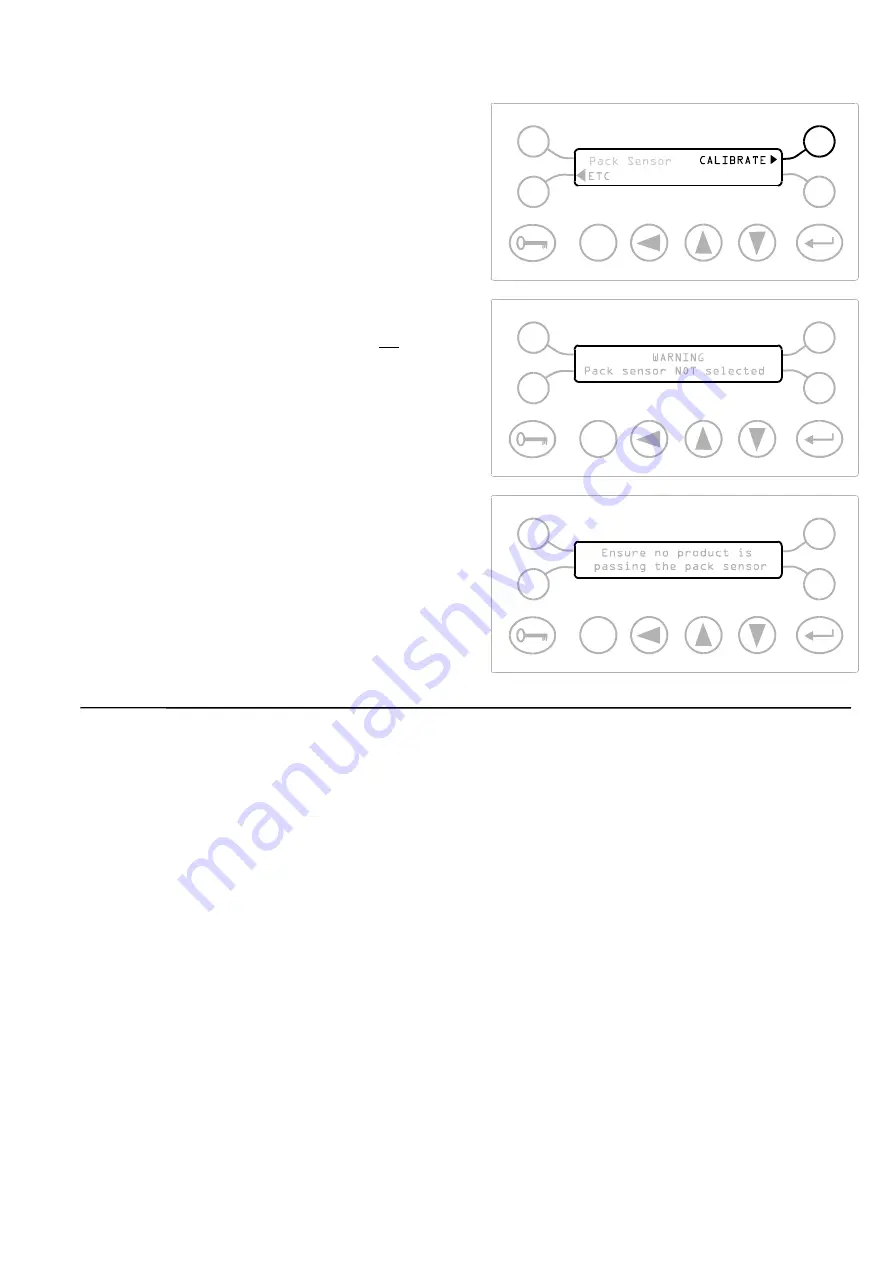
Press the soft key adjacent to CALIBRATE to start the
automatic calibration of the sensor.

When the CALIBRATE soft key has been pressed one
of two displays will appear, for a short time

a) If the display opposite appears you will be returned

to the previous display and the sensor will not be
calibrated.

This message will appear if NO was selected on
the previous display.

or

If ‘Ensure no product is passing the pack sensor’
appears the calibration will proceed.

b) After a short time the display will return to the

‘Pack Sensor Calibrate’ display shown above.
Press ETC to return to the Engineer Mode.

Содержание Signature

Страница 1: ...C Safeline Business Center 6005 Benjamin Road Tampa Florida 33634 USA Tel 813 889 9500 800 447 4439 Fax 813 881 0840 Web Site www metaldetection com Email sales safeline net service safeline net parts safeline net ...

Страница 2: ... and installation dependent parameters 5 Communicate with the detector using serial communications 6 Arrange a maintenance schedule using the printer option This manual is NOT intended as either 1 A Service Manual although some fundamental diagnosis is included in this manual 2 A Workshop Manual No detailed technical analysis either mechanical electrical or electronic is contained in this manual 3...

Страница 3: ...s document If the owner of the manual has any comments or suggestions as to the form content or presentation of this manual then they should write their suggestions and send them to the Technical Department at the Safeline address given on the title page Amendment Record If you receive an update for this manual then 1 Attach the update sheet s to the rear of the manual 2 In the row whose Amendment...

Страница 4: ...e process or its surroundings The above caption is used to draw the readers attention to a note of extra importance CAUTION This manual is regarded as an integral part of the detector This manual must always be kept with the detector for the whole of its operating life WARNING WHEN THIS CAPTION IS SHOWN ON THE EQUIPMENT IT IS USED TO INDICATE THE POSSIBILITY OF ELECTRIC SHOCK CAUTION WHEN THIS CAP...

Страница 5: ...y and the correct way to lift and support the detector during transportation CORRECT INCORRECT Safeline does not recommend the lifting or supporting of the detector by a person Always use suitable lifting or supporting apparatus Safeline will accept no liability for personal injury caused by attempting to lift or move the detector without the aid of a mechanical apparatus If supporting the detecto...

Страница 6: ...lectrical panels of your detector be opened by anyone other than a qualified electrical engineer Voltages in excess of 30 volts rms or 50 volts DC can in certain circumstances be lethal When working on electrical or electronic equipment always follow current health and safety practices and observe all other applicable regulations CAUTION For correct operation and to prevent any damage to the detec...

Страница 7: ...s Ensure all Invertors and variable speed drives in the proximity of the detector are installed in full accordance with their manufacturers instructions Where possible avoid placing any cables from Invertors variable speed drives etc in close proximity to the detector or the detector cables In particular take care to avoid placing the detector in the proximity of any equipment that generates elect...

Страница 8: ...chance of this occurring a Avoid any operations that may cause metal fragments to come into contact with the conveyor belt e g welding metal drilling or cutting in the vicinity of the conveyor belt b Clean the conveyor belt regularly 10 Orientation of contaminants Metal detector sensitivity is expressed as the diameter of the smallest spherical object which can be detected i e diameter of a ball S...

Страница 9: ...otection 5 Switched Power Output 5 Reject Relay 5 Detect Signal 6 Q A Due Overdue Output 6 Pack Sensor Requirements 6 Speed Sensor Requirements 6 Reject Confirmation Sensor Requirements 6 RS232 Serial Communications 6 Internal Counters 7 Spherical Sensitivity 7 Sensitivity Gradient 7 Timer Ranges 7 GENERAL 8 MECHANICAL INSTALLATION 8 Metal Free Zone MFZ 8 Figure 4 Metal Free Zone Guidelines Error ...

Страница 10: ...ect and Update Timer 42 Inverse Detection 42 Automatic Tracking option 43 Reject Count 43 Pack Count 43 Pack Sensor Setup 44 Security Setup 44 Speed setup 45 Auto tracking setup 45 Detection Buzzer 45 Reject inhibit Versions XT1 00 and XT1 01 only 45 Boost Mode 46 Language 46 Set Date and Time Option 47 Printer Handshake Option 47 AUTOMATIC SETUP 48 Introduction 48 Product Signal Cancellation 50 V...

Страница 11: ...ups A B or C 78 Sample size selection 78 tm1 TIMER 81 tm2 G TIMER NON GATED MODE 84 Introduction 84 tm2 settings 84 tm2G TIMER GATED MODE 88 tm3 G TIMER NON GATED MODE 94 Setting up Timer Type tm3 94 tm3 G TIMER GATED MODE 99 Setting up timer type tm3G in gated mode 100 SPEED SENSOR FOR THE TM3 AND TM3 G TIMERS 109 Speed Sensor Requirements 109 Speed Sensor Electrical Connections 109 Producing A R...

Страница 12: ...mmand Identifier E Error Codes 130 Command Identifier Q QA Lists and Displays 132 QA Operator commands 132 QA Inspector commands 132 EMULATION MODE 136 Objective 136 Principal of operation 136 CRC GENERATION 142 Method 142 C Program 143 TIMING DIAGRAMS FOR SERIAL COMMUNICATIONS 144 MAGNETIC LOOPS 147 RECOMMENDATIONS FOR THE USE OF INVERTERS 150 ATEX DIRECTIVE ERROR BOOKMARK NOT DEFINED ATEX system...

Страница 13: ...nnections 119 specification 119 Printouts 26 77 samples 121 Product effect 1 Product name 37 39 42 Product number introduction 3 setting 37 39 42 setting guide 24 Product signal cancellation 3 46 53 Product speed 27 47 66 Product Throughput Speed 5 P V R 4 Q Q A Inspector Mode 71 Q A Due Overdue 6 34 Q A Operator mode 78 security codes 76 78 Q A Support 4 Q A test time 34 R RC sensor 110 RCU Setti...

Страница 14: ...low Chart 36 Fig 15 Engineer Mode Flow Chart 39 Fig 16 Pack Sensor Mode Flow Chart 55 Fig 17 Security Setup Flow Chart 58 Fig 18 QA Inspector And Operator Flow Chart 66 Fig 19 Viewing Mode Flow Chart 76 Fig 20 Viewing Mode Flow Chart cont 77 Fig 21 Tm1 Timer Flow Chart 80 Fig 22 Tm2 Timer Flow Chart 83 Fig 23 Tm3 Timer Flow Chart 93 Fig 24 Rotary Encoder 109 Fig 25 Disc Construction 110 Fig 26 Det...

Страница 15: ... crystal display LED led Light emitting diode m metre mA milliampere MFZ Metal free zone MHz MegaHertz min minute mm millimetre ms millisecond non Fe Non ferrous NPN Negative positive negative type of transistor PNP Positive negative positive type of transistor PSC Product signal cancellation PVR Performance validation routines QA Quality assurance RMS Root Mean Square V Volt VA Volt amps W Watt 0...

Страница 16: ......

Страница 17: ... others Some products exhibit a product effect i e the product itself generates a signal in the same way as a metal particle This results from the bulk conductivity of the product at high frequency For most products usually dry products the product effect is negligible Wet or moist products e g meat sauces soups etc generate a large product effect signal which will influence the effective operatin...

Страница 18: ...ffect on the Non Ferrous Stainless Steel signals PHASE VALUE 00 20 0 40 0 60 0 80 0 90 0 100 0 120 0 140 0 160 0 AMPLITUDE STAINLESS STEEL FERROUS NON FERROUS VIBRATION 1800 VIBRATION Fig 2 Effect of Phase Control The phase control is used to minimise unwanted product effect signals Fig 3 shows a typical example It can be seen from Fig 3 that the phase control characteristic masks off some of the ...

Страница 19: ... timer group may be set as either of the following timer types Timer tm1 is a simple reject timer without any delay time Timer tm2 is a delayed reject timer for use in fixed speed applications Timer tm2G is a gated version of tm2 allowing for more accurate rejection of discrete product Timer tm3 is a variable speed version of tm2 Timer tm3G is a variable speed version of tm2G Automatic Setup This ...

Страница 20: ...directly from the metal detector to paper by using a printer Refer to Appendix C for sample printouts Timed requests for a check of the metal detector can be set Logging of rejects and logging of changes in the detectors settings can be set and these can be printed out on a timed basis e g for companies operating 8 hour shifts once every 8 hours Serial Communications The metal detector has a seria...

Страница 21: ... Internal Battery Discharge time typical 6 months from power off at temperature of 20 O C Battery life typical 5 years Nominal voltage 3 6 Volts D C Temperature Range Operating 10 C to 45 C 14 F to 110 F Storage 10 C to 50 C 14 F to 120 F Humidity Range Maximum relative humidity 93 for temperatures up to 45 O C Warm Up Time Zero seconds at an ambient temperature of 20 C Environmental Protection Pa...

Страница 22: ...A Pack Sensor Requirements Operating voltage 15 Volts D C Operating current 30 mA maximum Output type NPN or PNP open collector must be same as Speed Sensor Speed Sensor Requirements Operating voltage 15 Volts D C Operating current 30 mA maximum Output type NPN or PNP open collector must be same as Pack Sensor Output pulse width 10 ms minimum Output frequency 50 Hz maximum Reject Confirmation Sens...

Страница 23: ...eter of the wire is less than the spherical sensitivity setting the sample may not be detected in all orientations Sensitivity Ratios Dependent on frequency of coil system e g at 300 kHz Non Ferrous x 1 1 to 1 3 Fe diameter depending on the metal Stainless Steel x 1 2 to 1 5 Fe diameter depending on type most difficult to detect is type 316 Sensitivity Gradient Less than two diameters This is the ...

Страница 24: ...ise to inconsistent performance A little care when installing the detector will be rewarded by a consistent highly reliable metal detector performance MECHANICAL INSTALLATION Metal Free Zone MFZ To achieve optimum metal detector performance an area surrounding the aperture of the detector known as the MFZ should be kept free of metal The size of the MFZ will be dependent upon the aperture height A...

Страница 25: ...vibration from other machines is isolated from the detector Avoid supporting the detector head on or near vibrating structures and or machines subject to mechanical shock Position the detector head to allow easy access to the control panel Position the detector to allow removal of the control unit for servicing Electrical Connections WARNING If the detector is supplied as part of a system read all...

Страница 26: ...INSTALLATION 10 4618 021 Fig 5 Typical Metal Detector Conveyor ...

Страница 27: ...INSTALLATION 4618 021 11 Fig 6 Bearing Block And Mounting Foot Insulation Fig 7 Belt Joints Typically 100mm 150mm ...

Страница 28: ...wing procedure should only be carried out by qualified Safeline personnel or qualified Safeline agents Removing the Power Supply Box Lid 1 To remove the power supply box lid remove the four screws 2 Raise the power supply box lid 3 Lift the power supply box lid completely away from the power supply box To refit the power supply box lid ensure that the seal around the box lid is in place and undama...

Страница 29: ...29 30 31 32 33 34 35 36 37 38 39 40 41 42 43 44 45 46 47 48 49 50 51 52 53 54 55 56 20 21 22 23 24 25 26 27 28 57 58 59 60 61 62 63 64 65 66 67 68 69 70 71 72 73 74 L N E E Comms port 2 Remote Output Power input Switched power output Reject relay Relay 21 Latch Reset TXD RXD GND Remote Reset Latch Reset 15 V 15 V N C SPARE Pack Sensor Speed Sensor RCU Sensor Detector Head Cable Connections Detecto...

Страница 30: ...75 2 mm CONSTRUCTION 24 x 0 2 mm CURRENT RATING 6 AMP COLOURS BROWN LIVE BLUE NEUTRAL GREEN YELLOW EARTH 2 a RECOMMENDED CIRCUIT BREAKER DOUBLE POLE CURRENT RATING 3 AMP OR 4 AMP TYPE C CIRCUIT BREAKER TO BE MOUNTED CLOSE TO EQUIPMENT OR b RECOMMENDED FUSE RATING CURRENT RATING 4 AMP OR 5 AMP ANTI SURGE T ...

Страница 31: ...INSTALLATION 4618 021 15 Fig 10 Cable Gland Assemblies for Power Supply Unit ...

Страница 32: ...te one or more red LEDs on the 2 colour bargraph display a detect indicator in the centre of the control panel will illuminate The detect indicator will remain illuminated until the signal from the LED bargraph is equal to or less than 10 green LEDs The detect indicator will also illuminate if any faults occur with the detector Changing the metal detection characteristics can only be achieved by g...

Страница 33: ...ch Keys Explained Soft Keys The function of the four soft keys is controlled by the computer software and will change dependent upon where you are in the program Cursor Move Key This key is used to control the movement of the cursor bar when changing the setting of a numeric value A small cursor bar will appear under the active digit on the LCD display when a parameter is available for adjustment ...

Страница 34: ...value is showing on the digit press the Enter key 4 The cursor will move one position to the right and the entered digit will be replaced by an asterix character 5 Repeat steps 2 to 4 for all four digits 6 When the final digit is entered the detector will either a Go to the first display of the operating mode whose security code was successfully entered or b Return to the Running Mode display if a...

Страница 35: ...s on the left side of the display it will be indicated by a pointer which will change to a pointer when selected To change the numeric value of a particular setting use the following procedure 1 Enter security code and press the ETC softkey until the correct page is shown 2 Press the soft key adjacent to the parameter 2 to be adjusted The pointer will now point inwards towards the parameter and a ...

Страница 36: ... settings in the Settings Sheets at the rear of the manual There are four guides a Universal Settings Guide This guide lists the settings which control various operating characteristics of the detector These settings may be altered to suit the particular requirements of the application The word Universal is used as these settings affect all product numbers b Product Number Settings Guide The detec...

Страница 37: ...up on page 47 8 Reject Timers and subsequent timer sections on pages 45 and 82 9 Security Setup on page 47 NOTE In the majority of cases there will be no need to adjust the following items The following items are shown here for completeness Set the appropriate language for the displays Set today s date Set the current time If you want to prevent the reject device activating whilst setting up the d...

Страница 38: ... 48 13 Boost Mode on page 49 Set whether you want the internal buzzer to sound at detection If you are using the reject checking facilities of the detector If you will be using the Automatic Tracking option set up the universal settings for this feature At or near to full sensitivity a further 20 sensitivity improvement may be possible ...

Страница 39: ...racking on page 45 7 Go back to step 1 above for the next product to be set up 8 Product Number and Automatic Setup on page 40 9 Reject Inhibit on page 45 NOTE All of the following items may be set from the Engineer Mode of operation Select the required product number to set up next Select the timer group for the product number If the product number is an inverse detect application then select Inv...

Страница 40: ...he aperture when performing validation tests Set up the test interval so the detector will prompt the operator to perform Performance Validation Tests at regular intervals Set up the amount of time to allow after prompting for a test before the test is considered overdue Set up the security codes maximum of 9 separate codes for the operators who will be performing the Performance Validation Tests ...

Страница 41: ...st becoming DUE or OVERDUE Select whether a printer is to be used Select whether a printer will be permanently connected Enter a 4 digit identifier that will appear on all printouts useful where more than one detector is being operated Select what should appear on shift printouts Set the starting time for the automatic shift printouts Set the time between the automatic shift printouts How to Print...

Страница 42: ...r to the vibration characteristics of your system Set up the required timer groups to the appropriate timer type and settings Note this step is NOT required for timers which are synchronised to the product speed e g tm3 and tm3G timer types If you are using the reject checking facilities of the detector See the earlier guide How to Measure the speed of the product Step 1 Enter the Engineer securit...

Страница 43: ...tion sensitivity can be achieved by aligning the phase control to minimise the product signal When making adjustments to the detector for a particular product the user should ensure that product is passed through the detector aperture in its usual manner to create a worst case product effect condition Notes on Passing Product Through the Detector NOTE The product should be continually moving the d...

Страница 44: ...gh the detector in its normal manner If a product signal is observable on bargraph display ensure the product is flowing through the detector creating worst case product effect conditions refer to Notes On Passing A Product Through The Detector earlier 8 If a product signal is observable on bargraph display adjust the sensitivity control Sens page 43 so that the peak signal from the product gives ...

Страница 45: ...ay reduces Repeat the process increasing the phase setting in steps of 10 i e 20 30 40 50 60 etc until the null point is located For example if as the phase setting is increased there is clear reduction in signal from 80 to 90 and then from 90 to 100 the signal starts to increase again this indicates that the null point is between 80 and 100 11 Now reduce the phase setting in steps of 2 i e 98 96 ...

Страница 46: ...sted below 100 then improved spherical performance may be achieved by switching Operating Frequency to LOW and repeating the manual setup procedure omitting step 4 Under these conditions to ensure that the best sensitivity is achieved it is recommended that the manual setup procedure is carried out for both settings of Operating Frequency i e HIGH and LOW A comparison should then be made between t...

Страница 47: ...ODES VIEWING MODE SUPERVISOR MODE Q A INSPECTOR MODE ENGINEER MODE NAME 00 ETC Safeline Ltd ETC Pack Count Reject Count START OF PROGRAM ETC ETC Current Time PROD SENS Next QA Test PHASE 5 SEC TIME OUT PROD OPERATOR MODE NOTE If no QA test has been programmed to occur or the QA option is not fitted this line will not occur Fig 12 Running Mode Flow Chart ...

Страница 48: ...bserve the following display Serial Number Version and Model NOTE The display opposite contains vital information that will always be requested when contacting Safeline Make sure you have the above information to hand before telephoning Serial Number The serial number of your metal detector Model The right most number indicates the stagger frequency of your module The next four numbers indicate th...

Страница 49: ...ted It can be reset when in the Supervisor or Engineer modes Time This display shows the current time and the time of the next QA test Refer to the Engineer Mode section for information on setting the current time Refer to the QA inspector section for information on setting the Next QA Test time NOTE If no QA test is programmed or the QA option is not fitted then Next QA test will not appear PROD ...

Страница 50: ...OPERATING INSTRUCTIONS 34 4618 021 NOTE Auto Setup feature and adjustment of sens and phase are only available if operator access is set to Full Fig 13 Operator Mode Flow Chart ...

Страница 51: ... the ENTER key when the correct Product Number is displayed NAME Press the soft key adjacent to NAME to select the product by name Press the ENTER key when the correct product name is showing Sensitivity and Phase SENS Press the soft key adjacent to SENS to change the Sensitivity value Use the cursor key and up and down keys to select a value between 000 to 199 Press the ENTER key when the correct...

Страница 52: ...OPERATING INSTRUCTIONS 36 4618 021 Fig 14 Supervisor Mode Flow Chart ...

Страница 53: ...cursor key and up and down keys to select a number between 00 and 20 Press the ENTER key when the correct Product Number is displayed NAME Press the soft key adjacent to NAME to select the product by name Press the ENTER key when the correct product name is showing Sensitivity and Phase SENS Press the soft key adjacent to SENS to change the Sensitivity value Use the cursor key and up and down keys...

Страница 54: ...B or timer group C The currently selected timer group for the current product number is indicated by a flashing cursor over the group letter Press the soft key adjacent to the required group letter The flashing cursor will appear over the selected group letter When the cursor is indicating the intended group letter press the soft key adjacent to ETC to move to the next display Reject Count This di...

Страница 55: ...OPERATING INSTRUCTIONS 4618 021 39 Fig 15 Engineer Mode Flow Chart ...

Страница 56: ...ber between 00 and 20 Press the ENTER key when the correct Product Number is displayed NAME Press the soft key adjacent to NAME to edit the name or the current product number Press the ENTER key when the correct name has been entered Sensitivity and Phase SENS Press the soft key adjacent to SENS to change the Sensitivity value Use the cursor key and up and down keys to select a value between 000 t...

Страница 57: ...ft key next to the HIGH display to select this setting for product with no or small product effect signal LOW press the soft key next to the LOW display to select this setting for product with large product effect signal Power Drive This feature allows the level of high frequency power being fed into the coil system to be changed and is selectable for each product number For a small number of appl...

Страница 58: ...will appear If you are only intending to select the group to which the current product number will apply number 1 above then press the soft key adjacent to NO If you require to adjust the settings for the selected timer group then press the soft key adjacent to YES and refer immediately to the REJECT TIMERS section later in the manual Inverse Detection This feature allows the action of the reject ...

Страница 59: ... soft key adjacent to NO to disable Product Signal Cancellation for the current product number Note Product signal cancellation must have been set up by the Auto Setup facility for the current product number before YES can be selected Enabling Product Signal Cancellation for a product number that has the Automatic Tracking feature already enabled will cause the Automatic Tracking feature to be dis...

Страница 60: ...uring setting up operations NO Select NO for normal use Vibration setup Press the soft key adjacent to Vibration setup to enter the Vibration Setup menu Refer to the Vibration Setup section for more information Pack Sensor Setup Press the soft key adjacent to Pack Sensor Setup to enter the Pack sensor menu Refer to the Pack Sensor section for more information Security Setup Press the soft key adja...

Страница 61: ...ct ON so that the buzzer will sound when metal is detected OFF Select OFF to prevent the buzzer sounding when metal is detected Note The buzzer will always sound if a key is pressed or a fault occurs irrespective of the setting here Reject inhibit Versions XT1 00 and XT1 01 only WARNING DO NOT USE THIS FACILITY TO INHIBIT THE REJECT DEVICE DURING MAINTENANCE WORK ALWAYS REMOVE THE POWER SUPPLY TO ...

Страница 62: ...sensor to detect that a contaminated package has been rejected Note This display will only appear if YES is selected on the display above For timer types tm3 and tm3G the extn time is not used and window time is used Boost Mode YES Select YES to improve the sensitivity by 20 at a sensitivity of 199 NO Select NO for normal sensitivity at 199 Language LANGUAGE Use the soft key to scroll through the ...

Страница 63: ...t day Press the ENTER key when the correct day is set 24 HOUR Press the soft key adjacent to 24 HOUR to adjust the hour value of the current time Use the cursor key and up and down keys to select the correct hour Press the ENTER key when the correct hour is set The clock uses the 24 hour format MINUTE Press the soft key adjacent to MINUTE to adjust the minute value of the current time Use the curs...

Страница 64: ...he section below entitled Notes on passing product through the detector At worst the operator will be requested to pass the product through the aperture ten times If a pack sensor is to be used with the detector set up the pack sensor details before starting automatic setup for certain products the use of the pack sensor will speed up the operation of automatic setup The automatic setup supports I...

Страница 65: ...hen the coil system condition changes from no product to maximum product With individual or boxed cartoned product the worst case product effect condition occurs as the product enters and leaves the detector If the product is rectangular the product effect signal will generally be more severe if the product enters the detector aperture long edge leading as opposed to short edge leading The gaps be...

Страница 66: ...r When this display is showing pass the product through the aperture in its normal manner to create a worst case product effect signal for more details refer to Notes On Passing Product Through The Detector earlier If the detector does not detect any product being passed within a thirty second period the unit will revert back to the display from which automatic setup was started A pack sensor must...

Страница 67: ...sing metal samples through the aperture of the detector preferably on or in the product If required manually adjust Sensitivity page 53 to achieve the required spherical performance standard i e 1 0 1 5 2 0 Fe etc Note the sensitivity level for the bargraph may be limited by the vibration characteristics of the system If this is the case then ensure that manually increasing the sensitivity does no...

Страница 68: ...roduct passing through the aperture Repeat the automatic setup and ensure that no product is passed through the detector when instructed and that no product or metal is close to the aperture and influencing the detector 2 The automatic setup has requested the user to Pass product through aperture and no product has been sensed within the required period Repeat the automatic setup and ensure that t...

Страница 69: ...steps of 1 and at each step observe if the amplitude of product signal indicated on the bargraph display reduces For example if the automatic setup value is 90 and as the phase setting is increased there is a clear reduction in signal as we change from 90 to 91 and then from 91 to 92 the signal starts to increase again this indicates that the null point is between 90 and 92 5 Now reduce the phase ...

Страница 70: ...ity limit This display is used to manually or automatically set up the maximum sensitivity that will be set by the automatic setup feature of the detector The maximum sensitivity must be reduced in situations where the detector is subject to high vibration Press the soft key adjacent to sensitivity limit to manually set the sensitivity limit Press the ENTER key when finished Press the soft key adj...

Страница 71: ...OPERATING INSTRUCTIONS 4618 021 55 Fig 16 Pack Sensor Mode Flow Chart ...

Страница 72: ... NO if there is no sensor fitted Press the soft key adjacent to ETC to move to the next display Sensor distance This is the distance between the centre of the pack sensor and the infeed face of the detector Press the soft key adjacent to mm to change the value of sensor distance This distance should be entered in mm inches for U S version Photogated reject timers provide very precise and effective...

Страница 73: ...r for a short time a If the display opposite appears you will be returned to the previous display and the sensor will not be calibrated This message will appear if NO was selected on the previous display or If Ensure no product is passing the pack sensor appears the calibration will proceed b After a short time the display will return to the Pack Sensor Calibrate display shown above Press ETC to r...

Страница 74: ...NS 58 4618 021 Fig 17 Security Setup Flow Chart NOTE This flow chart shows the sequence when changing the Supervisor security code The sequence is the same for the Operator Engineer QA Inspector and Viewing security codes ...

Страница 75: ...e sensitivity and phase of a product as well as just changing the product number LIMITED Press the soft key next to LIMITED to prevent any person with an OPERATOR security code from being able to alter phase and sensitivity FULL Press the soft key next to FULL to allow any person with an OPERATOR security code to adjust phase and sensitivity The Security Setup sub routine allows the changing of th...

Страница 76: ...ity code i e OPERATOR SUPERVISOR ENGINEER QA INSPECTOR or VIEWING 3 If the soft key adjacent to SUPERVISOR is pressed the display opposite will appear 4 The cursor appears under the first digit Use the up and down keys to change the number and then press the ENTER key A replaces the number and the cursor moves to the next digit 5 Repeat Step 4 for the remaining three digits ...

Страница 77: ...the last digit has been set press the ENTER key and the display opposite appears 7 Press the ENTER key if the number is correct and return to the Engineer Mode 8 If the number is not correct press the RECALL key and carry out Steps 1 to 7 again ...

Страница 78: ...ensitivities to be used FAST This mode allows for faster speeds than the NORMAL mode to be achieved The additional performance increase of the NORMAL mode is NOT available in this mode VARIABLE This mode allows for products with varying speeds to be used The additional performance increase of the NORMAL mode is NOT available in this mode In most cases selecting NORMAL speed range will allow better...

Страница 79: ...speed of the product to be set either manually or automatically Press the soft key adjacent to product speed to manually set the product speed Press the ENTER key when finished Press the soft key adjacent to Auto Adjust to automatically set the product speed U S version only ...

Страница 80: ... flash alternatively between the Safeline ltd and Auto Tracking message to indicate that tracking has been enabled Automatic tracking maximum rate This display is used to set the maximum amount that the phase is allowed to change between two succesive pack measurements Press the soft key adjacent to Maximum rate to change the maximum allowable rate of phase change per pack Press the ENTER key when...

Страница 81: ...Press the ENTER key when the correct maximum span is showing Automatic tracking damping This number corresponds to how quickly the automatic tracking will react to changes in phase and sensitivity Press the soft key adjacent to Damping to change the speed of response of the automatic tracking Press the ENTER key when the correct damping is showing NOTE A low value for damping means a quick respons...

Страница 82: ...OPERATING INSTRUCTIONS 66 4618 021 Fig 18 QA Inspector And Operator Flow Chart ...

Страница 83: ...mber to record all settings on the Settings Sheets at the rear of the manual Printer Although effective as a feature in its own right the PVR is most effective when used in conjunction with a printer the printer will provide a date and time stamped hard copy print out showing when the detector was tested and by whom The hard copy print out can be used to demonstrate authorised personnel s complian...

Страница 84: ...and two digits could be the metal detector number Press ENTER when the required line identification is showing Printer Fitted YES Select YES if a printer is installed NO Select NO if there is no printer installed Printer Fixed Portable Portable printers will not give a data collection unit not ready message if a QA test is performed without a printer attached Fixed printers will always give the me...

Страница 85: ...o include the date and time of all reject relay operations which have occurred since the last shift report in the print out of the current shift report OUT Select OUT to prevent the print out of the data and time of all reject relay operations between shift printouts At the Modified Settings display press a soft key adjacent to IN or OUT IN Select IN to include certain settings which have been cha...

Страница 86: ...en 0 and 59 Use the up and down keys to change the value Press the ENTER key when the correct number of minutes is shown NOTE Setting the Shift Report Interval time to 0 00 will disable the shift report facility Shift Report Start Time This display allows the QA inspector to specify a start time for the automatic printing of shift reports H Press the soft key adjacent to H to adjust the hours valu...

Страница 87: ...rect number of minutes is shown NOTE Setting the time to 0 00 will disable requests for timed performance checks Overdue Period This display allows the QA inspector to adjust the time period allowed following a performance check request before the test becomes overdue Once the test becomes overdue the REQUEST FOR PERFORMANCE CHECK message is replaced with OVERDUE FOR PERFORMANCE CHECK At the same ...

Страница 88: ... setting of up to nine QA operator security codes Press the soft key adjacent to the dotted line to select a QA operator number 1 to 9 Press the soft key adjacent to and change the code number using the cursor key and up and down keys Press the ENTER key to store the new code in memory Repeat the operation for as many QA Operator s as required Press the ETC key to return to the first display of th...

Страница 89: ...d by the QA Inspector See the Shift Report Options section earlier a Any reject relay operations during the shift and b Any settings that have been modified during the shift 2 After printing the shift report the detector will clear all the current shift information and start collecting information for the next shift QA Inspector Test Menu From the QA Inspector Mode press the soft key adjacent to T...

Страница 90: ...rity codes for QA Operators modes Code 1000 QA Operator 1 Mode Code 2000 QA Operator 2 Mode etc Code 9000 QA Operator 9 Mode Carrying Out a Performance Check Notes on the Test Sample Always pass the test sample through the detector aperture with the product If the detector is inspecting individual products prepare a sample pack s with the sample s to be tested placed at the centre rear of the pack...

Страница 91: ...he detector front panel 4 Where applicable check that the reject device operates to reject the test sample 5 Press the soft key that is adjacent to the test result e g PASSED or FAILED 6 The display shown previously will re appear 7 If there are more test samples to be checked then repeat steps 1 to 4 for each sample Worst case testing Follow the guidelines below to ensure that the detector is tes...

Страница 92: ...OPERATING INSTRUCTIONS 76 4618 021 Fig 19 Viewing Mode Flow Chart ...

Страница 93: ...e setup from the Engineer Mode The sequence of displays is shown on the flow chart Figure 19 Each display can be viewed in turn by pressing the soft key adjacent to ETC Note In the Viewing Mode it is only possible to see product related settings such as phase and sensitivities for the currently selected product number Similarily frequency dependent settings will only be seen for the current freque...

Страница 94: ... The different timer settings may then be selected as required Both timer group selection and timer type setting may be made in the Engineer Mode but only timer group selection for a product number can be made from the Supervisor Mode Important notes for timer setup Sample size selection Small size metal contaminants should be used during the setting of the timers the use of large contaminants wil...

Страница 95: ...or s beam before they reach the reject device à Ensure the pack sensor and reflector if fitted are not affecting the metal detector by infringing upon the metal detectors metal free zone à At conveyor speeds of 61 m min 200 ft min or greater the pack sensor must not be positioned less than 0 5 m 1 5 feet from the reject device à The height and alignment of the pack sensor beam must be set so that ...

Страница 96: ...p GO BACK TO ENGINEER MODE B C A ETC YES NO tm2 G tm3 G SEE THE tm3 G MODE SEE THE tm2 G MODE Timer type tm1 ETC Timer X type tm1 set updated tm1 REJECT TIME ms GO BACK TO ENGINEER MODE GO BACK TO ENGINEER MODE GO BACK TO ENGINEER MODE Enter key pressed See fig 22 Fig 21 Tm1 Timer Flow Chart ...

Страница 97: ...o step 3 1 Press the soft key adjacent to the required group letter A B or C 2 If you only need to select the timer group for the current product number and not adjust any of the timer group properties then a Select the soft key adjacent to NO and go back to the Engineer Mode section CAUTION Although NO was selected the group will be changed to the group letter selected in 1 else b Select the soft...

Страница 98: ...ey to accept the new settings 7 Press the Enter key a second time to proceed to the next display 8 The display shown opposite will appear for five seconds before returning to the Engineer Mode display Testing the Reject Device 9 Check the reject device operates correctly with different sizes of metal contaminant 10 If for any reason the setting of the tm1 timer is not correct return to step 1 and ...

Страница 99: ...l required YES tm2 Gated FROM ENGINEER MODE Timer X type tm2 G set updated GO BACK TO ENGINEER MODE NO Enter pressed ETC tm2G SIGNAL DELAY REJECT TIME ms ms ETC tm2G SYNC DELAY WINDOW TIME ms ms tm2G SIGNAL DELAY REJECT TIME ms ms NO Enter pressed NO YES See fig 20 Fig 22 Tm2 Timer Flow Chart ...

Страница 100: ...rent product number should use or b Select which timer group the current product number should use AND adjust the timer group settings such as timer type reject time signal delay etc REMINDER If you have already selected the timer group and pressed YES to updating the group as per the Engineer Mode section earlier then proceed to step 3 1 Press the soft key adjacent to the required group letter A ...

Страница 101: ...osite appears press the soft key adjacent to NO else b Proceed to step 5 5 Press the soft key adjacent to SIGNAL DELAY a For packaged or separate products i Place the metal contaminant at the rear trailing edge of the product ii Pass the product with the metal contaminant attached through the detector aperture ensuring that the product does not slip or skew iii Use the cursor Up and Down keys to a...

Страница 102: ...the product with the metal contaminant attached through the detector aperture ensuring that the product doesnot slip or skew iii Use the cursor Up and Down keys to adjust the Reject Time so that the metal contaminant is rejected consistently and accurately b For loose products i Place the metal contaminant on the centre of the conveyor belt ii Pass the product with the metal contaminant through th...

Страница 103: ... device operates correctly with different sizes of metal contaminant b For loose products i Check the setting of tm2 by passing the product and metal contaminant through the aperture of the detector ii Check the reject device operates correctly with the metal contaminant at different positions on the conveyor belt iii Check the reject device operates correctly with different sizes of metal contami...

Страница 104: ... type reject time signal delay etc NOTE REMINDER If you have already selected the timer group and pressed YES to updating the group as per the Engineer Mode section earlier then proceed to step 3 1 Press the soft key adjacent to the required group letter A B or C NOTE Remember to record all settings on the Settings Sheets at the rear of the manual tm2G settings 1 Signal Delay 2 This is the time ta...

Страница 105: ... in 1 else b Select the soft key adjacent to YES and proceed to step 3 3 Press the soft key adjacent to tm2 G 4 a If the display opposite appears i Press the soft key adjacent to NO if you are setting up the timer for the first time else ii If you are fine tuning an existing tm2G setting press the soft key adjacent to YES then go to step 10 else b Proceed to step 5 In the following displays X repr...

Страница 106: ...of the pack reaches it 6 Press the soft key adjacent to REJECT TIME a Place the metal contaminant at the rear trailing edge of the product package b Pass the product with the metal contaminant attached through the detector aperture ensuring that the product does not slip or skew c Use the cursor Up and Down keys to adjust the Reject Time in a way that would reject the pack if it was positioned cor...

Страница 107: ... 12 to ensure that the window time is being measured correctly and is repeatedly calculating the same value within 10 14 Ensure that the pack sensor beam is clear of any packs or products 15 Select the soft key adjacent to the SYNC DELAY When the Sync delay is selected the detect led and buzzer will sound permanently a Pass the product through the detector aperture ensuring that the product does n...

Страница 108: ...osite will appear for five seconds before returning to the Engineer Mode display Testing the Reject Device 22 a Check the setting of tm2G by passing the product and metal contaminant through the aperture of the detector b Check the reject device operates correctly with the metal contaminant at both the front and rear of the pack c Check the reject device operates correctly with different sizes of ...

Страница 109: ... required YES tm3 Gated FROM ENGINEER MODE Timer X type tm3 G set updated GO BACK TO ENGINEER MODE NO Enter pressed ETC tm3G SIGNAL SHIFT REJECT TIME ms ms ETC tm3G SYNC SHIFT WINDOW SHIFT ms ms tm3G SIGNAL SHIFT REJECT SHIFT ms ms NO Enter pressed NO YES See fig 20 Fig 23 Tm3 Timer Flow Chart ...

Страница 110: ...ettings such as timer type reject shift signal shift etc NOTE REMINDER If you have already selected the timer group and pressed YES to updating the group as per the Engineer Mode section earlier then proceed to step 3 1 Press the soft key adjacent to the required group letter A B or C NOTE EXPLANATORY NOTE The tm3 and tm3G timer modes continually refer to terms such as SIGNAL SHIFT REJECT SHIFT SY...

Страница 111: ...he soft key adjacent to NO else b Proceed to step 5 5 Set the product line to its mid range speed 6 Press the soft key adjacent to SIGNAL SHIFT a For packaged or separate products 1 Place the metal contaminant at the rear trailing edge of the product 2 Pass the product with the metal contaminant attached through the detector aperture ensuring that the product does not slip or skew 3 Use the cursor...

Страница 112: ...Pass the product with the metal contaminant through the detector aperture ensuring that the product does not slip or skew iii Use the cursor Up and Down keys to adjust the Reject Shift so that the metal contaminant is rejected consistently and accurately b For loose products i Place the metal contaminant on the centre of the conveyor belt ii Pass the product with the metal contaminant through the ...

Страница 113: ...2 a For packaged or separate products i Check the setting of tm3 by passing the product and metal contaminant through the aperture of the detector ii Check the reject device operates correctly with the metal contaminant at both the front and rear of the pack iii Check the reject device operates correctly with different sizes of metal contaminant iv Repeat i to iii above at the lowest and highest s...

Страница 114: ...ant at different positions on the conveyor belt iii Check the reject device operates correctly with different sizes of metal contaminant iv Also check the reject device operates correctly with two metal contaminants spaced at different distances apart on the conveyor belt v Repeat i to iv above at the lowest and highest speeds 13 If for any reason the setting of the tm3 timer is not correct return...

Страница 115: ...JECT SHIFT SYNC SHIFT etc The word shift when used in these context refers to the distance the product will move or shift between successive pulses on the speed sensor input Thus if a speed sensor has a shift of 10 cm then a REJECT SHIFT of 5 is equivalent to a product moving a distance of 5x10 cm 50 cm For instructions on calculating the shift distance for your application refer to Appendix A tm3...

Страница 116: ...djacent to the required group letter A B or C 2 If you only need to select the timer group for the current product number and not adjust any of the timer group properties then a Select the soft key adjacent to NO and go back to the Engineer Mode section CAUTION Although NO was selected the group will be changed to the group letter selected in 1 else b Select the soft key adjacent to YES and procee...

Страница 117: ...gnal Shift so that the reject device operates just as the front edge of the pack reaches the centre of the reject device 7 Press the soft key adjacent to REJECT SHIFT a Place the metal contaminant at the rear trailing edge of the product package b Pass the product with the metal contaminant attached through the detector aperture ensuring that the product does not slip or skew c Use the cursor Up a...

Страница 118: ...Pass the product sample through the pack sensor beam ensuring that it does not skew or slip on the conveyor The metal detector will automatically measure the window shift and display this instead of the RUN message 14 Repeat steps 12 and 13 to ensure that the window shift is being measured correctly and is repeatedly calculating the same value within 10 15 Ensure that the pack sensor beam is clear...

Страница 119: ...ccept the new settings 18 Press the soft key adjacent to ETC 19 Press the soft key adjacent to REJECT TIME a Place the metal contaminant at the front or rear edge of the product package b Pass the product with the metal contaminant attached through the detector aperture ensuring that the product does not slip or skew c Use the cursor Up and Down keys to adjust the Reject Time until the pack is rej...

Страница 120: ...ector b Check the reject device operates correctly with the metal contaminant at both the front and rear of the pack c Check the reject device operates correctly with different sizes of metal contaminant d Repeat a to c above at the lowest and highest speeds 24 If for any reason the calibration of the tm3G timer is not correct return to step 1 and repeat all the steps ...

Страница 121: ... to receiving a signal from the RC Sensor This period plus a small safety margin is known as the RC Extension time and must be entered by the user The RCU achieves this by knowing when the Reject Mechanism is to be activated and deactivated Following reject deactivation the RCU waits for a signal generated via the Reject Mechanism or the rejected product to confirm reject operation This signal is ...

Страница 122: ... Pass a test sample through the detector aperture to trigger the detector The reject mechanism will respond according to its settings When the reject mechanism is released and moves from reject back to the pass position the RC Sensor confirms reject operation providing the extension time setting is long enough 7 If the detector goes into a reject fault condition increase the extension time by a fu...

Страница 123: ...the detector signals a fault condition 12 Increase the RC window time by 300 ms and press the ENTER key to enter the new value into memory Packaged Product Variable Speed Applications 1 Set the line speed to its slowest speed 2 From the running mode display press PROG EXIT key 3 Enter the Engineers security code 4 Press ETC soft key until the Reject Confirmation display is reached 5 Press the RC w...

Страница 124: ...th of the following a The Reject Mechanism has failed to operate or failed to operate at the correct time b The RC Sensor has not signalled the RCU to confirm reject operation The detector will clear the display when the RCU is reset Input output Fault This display indicates that a fault has occurred in the input output circuitry from the Module to the RCU this could be a connection or I C fault w...

Страница 125: ...or must be the same output type NPN or PNP Output Voltage 15 V minimum Output Current 10 mA minimum Output Waveform Pulse output Pulse width 10 ms minimum Frequency 50 Hz maximum Speed Sensor Electrical Connections Refer to the Installation section Connect the sensor to the terminals labelled Speed Sensor Producing A Rotary Encoder Using A Proximity or Photo electric Sensor Fig 24 Rotary Encoder F...

Страница 126: ... The speed sensor provides digital pulses in relation to the distance moved by the conveyor The incremental distance moved between pulses is known as the SHIFT distance and is the smallest interval measurable by the detector i e its resolution Table A 1 can be used to determine the shift distance for your system Using distance d between the detection and rejection points see Figure A 3 below follo...

Страница 127: ...abulated limit then choose the next point up providing as in our example distance d still lies within limits Shift Distance 6 5 mm 0 25 inch 13 mm 0 5 inch 19 mm 0 75 inch 25 5 mm 1 0 inch 32 mm 1 25 inch Detection to Rejection Minimum 191 mm 7 5 inch 381 mm 15 inch 572 mm 22 5 inch 762 mm 30 inch 953 mm 37 5 inch Distance d Maximum 635 mm 25 inch 1270 mm 50 inch 1905 mm 75 inch 2540 mm 100 inch 3...

Страница 128: ...any data collection device Requirements Of Your Serial Printer Currently the printer driver supplied as standard with the metal detector is designed to drive either a dot matrix type or an Epson TML60 II printer The format of the information being output by the metal detector is in columns of up to 42 characters The serial communication parameters of your printer must be setup as follows Baud rate...

Страница 129: ...ire CTS DSR or DCD to be at active levels However it is accepted good practice to connect these signals together as shown 2 The printer pin numbers shown are for an RS232 25 way D type connector if your printer uses a 9 way D type connector consult the printer manual for the correct pin numbers ...

Страница 130: ... 02 170 000 00 A 03 170 000 00 A 04 170 000 00 A 05 170 000 00 A 06 170 000 00 A 07 170 000 00 A 08 170 000 00 A 09 170 000 00 A 10 170 000 00 A 11 170 000 00 A 12 170 000 00 A 13 170 000 00 A 14 170 000 00 A 15 170 000 00 A 16 170 000 00 A 17 170 000 00 A 18 170 000 00 A 19 170 000 00 A 20 170 000 00 A Prod Freq Inverse Power P S C Tracking 00 1 NO HIGH 01 1 NO HIGH NO NO 02 1 NO HIGH NO NO 03 1 ...

Страница 131: ...ck span 30 00 Auto Track damp 5 Boost NO Printer handshake SW Current Prod No 00 QA Settings Printout QA Settings Line ID 0000 Printer YES Printer FIXED Relay Rpt YES Settings Rpt YES Report Int 00 00 Test Int 0 00 Overdue Int 0 00 Alarm DUE Prod No Fe N Fe S S 00 0 0 0 0 0 0 01 0 0 0 0 0 0 02 0 0 0 0 0 0 03 0 0 0 0 0 0 04 0 0 0 0 0 0 05 0 0 0 0 0 0 06 0 0 0 0 0 0 07 0 0 0 0 0 0 08 0 0 0 0 0 0 09 ...

Страница 132: ...46 21 Oct 95 09 00 47 21 Oct 95 09 00 48 21 Oct 95 09 31 03 21 Oct 95 10 05 59 21 Oct 95 10 06 00 Modified Settings Date Time 21 Oct 95 09 01 15 Prod No 01 Sens 180 Timer C Rej Count RESET Pack Count RESET Current Prod No 00 Date Time 21 Oct 95 10 25 15 Prod No 02 Sens 185 Timer A Reject Inh YES Current Prod No 01 Date Time 21 Oct 95 10 27 46 Reject Inh NO Current Prod No 01 SHIFT REPORT END ...

Страница 133: ...ce Check Date Time 21 Jan 95 10 45 00 Line ID 0205 Operator QA INSPECTOR Prod No 01 Sens 156 Phase 05 00 Timer B Material FERROUS Size 1 5mm Dtection YES Reject Rly YES Result PASSED Material STAINLESS STEEL Size 1 5mm Detection YES Reject Rly YES Result PASSED ...

Страница 134: ...D COMMAND ETX CRC 1 The message starts with STX HEX 02 indicating start of message 2 G and M are identifiers that are contained in every message 3 COMMAND is made up of IDENTIFIER VALUES LIST IDENTIFIER is one of a series of letter or letter number combinations detailed in the tables below VALUES LIST are decimal values with leading zero suppression unless otherwise specified separated by comma s ...

Страница 135: ...tiated by the host to change the settings of the detector or to read the settings of the detector 3 Detector responses to host commands 4 These messages are responses to host commands and are sent by the detector If in the unlikely case of the serial output buffers being filled higher priority messages will be transmitted at the expense of lower priory messages Test Mode For the purpose of checkin...

Страница 136: ... group A t 1 Timer group B t 2 Timer group C a Frequency offset single digit number in the range 0 1 Note If parameter n is 0 then c1 must be 00 00 Product Settings P c n c in out Printer Handshake n 0 HW n 1 SW Printer Handshake X D d c D d c D out in in Counter values d reject counter four digit number in the range 0 9999 c pack counter eight digit number in the range 0 16777214 d 1 Reset reject...

Страница 137: ...heck n 512 Inverse detect must be deselected n 1024 Timer must be gated for this option n 2048 FAULT Pack sensor blocked n 4096 CAUTION Pack sensor not selected n 8192 Ensure no product is passing the pack sensor n 16384 CAUTION Auto tracking disabled n 32768 Power drive failed o 1 CAUTION P S C has been disabled o 2 P S C not captured use the automatic setup o 4 CAUTION Stored signal cleared o 8 ...

Страница 138: ... which extended faults are present Current fault status X f m n f m in out in Inverse detect m product number a two digit number in the range 0 20 n 0 NO n 1 YES Inverse detect for product number m P G n in out Message Length The number of characters or bytes from after G n to but excluding ETX in every communications message n A two digit number with leading zeroes in the range 0 99 For example t...

Страница 139: ...0 60000 with timer types tm3 and tm3G all times in milliseconds Reject Confirmation Extension or Window time L n o L o in out in Power high low setting n product number a two digit number in the range 0 20 o 0 LOW n 1 HIGH Power high low setting P M n in out Message number n A four digit number with leading zeroes in the range 0 9999 This number is incremented for each message sent wraparound to z...

Страница 140: ...or product number m P R n R out in Detection status n 0 Normal n 1 Detection Detection Status X r n r in out in Pack sensor fitted n 0 NO n 1 YES Pack sensor fitted X S a b c d S in out in Security codes Each of these is a four digit number in the range 0 9999 a Supervisor code b Engineer code c Viewing code d QA Inspector code Security codes X s n s in out in Pack sensor calibration n 0 Pack sens...

Страница 141: ...0 99 m The month a two digit number in the range 1 12 d The day of the month a two digit number in the range 1 31 Date X V f n V f in out in Sensitivity limit f Frequency offset a single digit number in the range 0 1 Must be 0 for single frequency heads n Sensitivity limit a three digit number in the range 0 199 Sensitivity limit F W h m W in out in Time See Note 2 h The hour a two digit number in...

Страница 142: ...ber in the range 0 20 s A string of alphanumeric characters s must be 14 characters long Product name P z02 SEE LATER FOR DETAILS OF IDENTIFIER z02 X z03 v z03 in out in Product speed v A fixed point number of the speed m min in the range 0 5 200 0 U S version only v A fixed point number of the speed feet min in the range 1 6 656 1 Product speed X z05 d z05 in out in Sensor distance d Sensor dista...

Страница 143: ...inated a minimum count of 200 would be necessary 6 Note on timer types Not all the timer types use all the parameters that are transmitted with the T identifier However the host must always send the correct number of variables to the detector and similarly the detector always responds with the correct number of variables To alleviate this restriction the detector will accept the value 0 for those ...

Страница 144: ... Transmitting this command is equivalent to selecting NO on the keypanel b99 This command is sent when the host wishes to abort the automatic setup procedure and return to normal operation This is equivalent to pressing the front panel key PROG EXIT during the automatic setup and will cause the same action to occur in the metal detector For a description of the states see the Auto Setup Flowchart ...

Страница 145: ...ng may be in error Product YES cancellation NO Product cancellation NOT operating Product adjustment completed Obtaining product information 1 Obtaining product information 2 Setup without the additive Setup with the additive Repeat the tests YES with an additive NO WARNING Pack sensor not fitted Automatic setup FAILED Automatic setup timed out Automatic setup aborted via the keyboard or comms 1 2...

Страница 146: ...eived command etc 4 Bounds Error A value was outside acceptable limits Please refer to the previous tables for the range that values can take 5 Not used Reserved for future development m is the minor error number and takes on a different meaning dependent upon its preceding major error number Table D 3 Minor error codes m minor error Description of error 0 No Error this is sent only with the major...

Страница 147: ... panel Security key during the automatic sensitivity limit and will cause the same action to occur in the metal detector Commands the metal detector may transmit The following command will be transmitted in response to a j command above or automatically during the operation of automatic sensitivity limit j n n is a number indicating the state of the automatic sensitivity limit s progress the numbe...

Страница 148: ...sult o 0 Failed o 1 Passed Request last values of m n and o used by the detector P Q02 Q09 Reserved for later use X QA Inspector commands Command 1 2 Direction 3 Description Type 4 Q10 n in out Printing n 0 Print ing all settings n 1 Print ing shift reports X Q11 n Q11 in out in Line identification number n 4 digits number Line Identification Number X Q12 n Q12 in out in Printer Selected n 0 NO n ...

Страница 149: ... Maximum overdue period must be less than half of Test Interval and less than 04 59 Overdue Period X Q19 n Q19 in out in Alarm if Due Overdue Setting n 0 DUE n 1 OVERDUE Alarm if Due Overdue Status X Q20 n o Q20 n in out in QA Operator Number and Code n Operator number a single digit number in the range 1 9 o 4 digit code for the operator n in the range 0 9999 QA Operators code X Q21 n Q21 in out ...

Страница 150: ... below z02 99 This command is sent when the host wishes to abort the automatic product speed procedure and return to normal operation This is equivalent to pressing the front panel security keyduring the automatic product speed and will cause the same action to occur in the metal detector Commands the metal detector may transmit The following command will be transmitted in response to a z02 comman...

Страница 151: ... the bargraph and detection messages A n and R n will be suppressed After completing the automatic product speed these messages will be resumed if they had been enabled prior to commencing the automatic productspeed 2 The command z02 1 cannot be sent if either Automatic Setup or Automatic sensitivity limit is running ...

Страница 152: ...ommand set supporting emulation mode Command 1 2 Direct 3 Description Notes z15 n z15 In Out In Emulation mode enabled disabled n 0 emulation disabled n 1 normal emulation enabled n 2 fast emulation enabled See Emulation Mode description for more details Emulation mode Normal fast emulation mode z16 min max z16 In Out In Fast emulation mode timing min min gap time between messages ms default 20ms ...

Страница 153: ...when no remote panel is used The PCI protocol is unaffected Default mode after hardware reset 2 Normal Emulation mode This mode of operation is achieved by using the emulation commands utilizing the existing protocol format i e no alterations to the existing protocol format are required The additional commands to implement this mode are z15 z20 z22 Note In this mode the z20 command works under the...

Страница 154: ... info data transmitted is packed as described under Screen package format The z20 command in normal emulation mode The command behaves like any other command under the PCI protocol The screen update has to be requested by the host The message format would look as follows STX G VALUE M VALUE z20 ENCODED DATAPACK ETX CRC The z20 command in fast emulation mode The z20 cmd is automatically transmitted...

Страница 155: ...rd Windows machine In particular LCD Code Character Windows character code 0 not used 1 or 0x25BA 2 or 0x25C4 3 7 Soft character cache 0 5 0xDF 0x00B0 0xE1 ä 0x00E4 0xEE ñ 0x00F1 128 255 Japanese other special characters The cursor is encoded as follows Bit Content 7 Underline cursor 6 Block blinking cursor 5 0 Cursor position 0 23 is the first row 24 47 is the second row If neither bits 6 or 7 ar...

Страница 156: ...OFT_oACUTE 12 0x00F8 ø SOFT_oSLASH 13 0x00F6 ö SOFT_oUMLAUT 14 0x00F1 ñ SOFT_nTILDE 15 0x00C5 Å SOFT_ACIRCLE 16 0x00E5 å SOFT_aCIRCLE 17 0x0141 Ł SOFT_LSLASH 18 0x0142 ł SOFT_lSLASH 19 0x015A Ś SOFT_SSLASH 20 0x015B ś SOFT_sSLASH 21 0x0106 Ć SOFT_CSLASH 22 0x0107 ć SOFT_cSLASH 23 0x017B Ż SOFT_ZCIRCLE 24 0x017C ż SOFT_zCIRCLE 25 0x0143 Ń SOFT_NSLASH 26 0x0144 ń SOFT_nSLASH 27 0x0118 Ę SOFT_ECOMMA ...

Страница 157: ...urther keys will overwrite the unprocessed one This command is always available regardless of z15 setting In order to clear a fault via the local panel the soft key 2 is pressed and held down for a certain time period To simulate this action it is necessary to send multiple SKEY2 emulated keys z22 S2 Simultaneous use of local and remote panel The local and remote key panel can be used simultaneous...

Страница 158: ...l with no leading zero suppression Polynomial used G x x 16 x 12 x 5 1 i e CCITT Data is processed Least Significant Disc LSB of character first and transmitted high byte and high nibble to low byte and low nibble The CRC accumulator is initialized to FFFF before every packet is started Example CRC Numbers MESSAGE STRING CRC HEX T 1B26 THE 44BE THE QUICK BROWN FOX 0123456789 DF91 Note The CRC does...

Страница 159: ...int blkcrc unsigned char bufptr unsigned int crcres unsigned int count int i for i 1 i count i bufptr do for whole block bytecrc bufptr crcres do CRC for 1 byte return crcres end blkcrc unsigned int bytecrc unsigned char bufptr unsigned int crcres unsigned int j ch Q ch unsigned int bufptr get char to int format for j 1 j 8 j do each bit LSB first Q crcres 0x0001 ch 0x0001 Q 1 if either crcres or ...

Страница 160: ...IMING DIAGRAMS FOR SERIAL COMMUNICATIONS Fig 27 D 1 Host Query of Detector Fig 28 D 2 Host Command type 1 causes change in value of detector variable Fig 29 D 3 Host Command type 2 causes NO change in value of detector variable ...

Страница 161: ...SETTINGS SHEET 4618 021 145 Fig 30 D 4 Event Occurence inside detector Table D 4 Absolute maximum timings Time Minimum ms Maximum ms T1 0 250 T2 0 250 T3 0 250 T4 200 T5 0 250 ...

Страница 162: ... 4618 021 146 Event E g Detection fault Fig 31 Event driven message interrupting normal ack nak response to the host Event message T0 1 55 T i m e ACK Dnnn xxx HOST ACK DETECTOR Host command and detector response ...

Страница 163: ...n Section The magnetic field from the detector can radiate into the conveyor frame this in turn would create minute electrical currents which would flow through the closed path or loop created by the rollers mounted across the conveyor frame Problems with loops can be avoided by opening or closing the loop in a permanent manner It is the intermittent nature of a loop path that causes intermittent ...

Страница 164: ...Software Version Notes Product Details Nr Product name Sens Phase Operating frequency Power Drive Timer group Inverse detect Automatic tracking P S C 0 000 00 NO NO 1 2 3 4 5 6 7 8 9 10 11 12 13 14 15 16 17 18 19 20 Engineer Mode Settings Detection buzzer Pack sensor fitted Operator access Speed range Detector speed Reject inhibit Reject confirmation Reject confirm time Boost mode Language Printer...

Страница 165: ...12 13 14 15 16 17 18 19 20 Distributor use only Com1 A S reject inhibit Reject confirmation option Performance check option Product cancellation option Switched frequency Fe Phase Q A Setup Line id Printer Printer Reject relay operations Modified settings Shift report interval Shift report start Test interval Overdue period Alarm if due overdue Automatic tracking option Auxiliary output ...

Страница 166: ...ned cables should be grounded at suitable intervals where possible 4 Remove insulation only where screening clamps are shown to provide good earth continuity at that point 5 Do not run the power cables I O cables and signal cables of the inverter in parallel with each other and do not bundle them 6 Use twisted shield cables for the detector connecting and the control signals 7 Ground inverter moto...

Страница 167: ...lar inspection of plastic and gasket materials should be made to ensure no wear or damage has occurred that may affect the ingress integrity of the system The power supply module enclosure can in some cases accommodate additional glands that can be fitted by the end user If new glands or blanking plugs are fitted by the end user they must ensure that the fitting are of metal construction and that ...

Страница 168: ...n non metallic parts with a dry cloth CAUTION Refer to manual for connection details ACHTUNG Vor inbetriebnahme bedienanleitung beachten Voir le manuel ATTENTION CAUCION avant tout cablage por conection detalla Le refiere a manual Un risque d électricité statique peut exister Ne pas nettoyer les parties non méalliques avec un chiffon sec Es gibt gegebenfalls Probleme mit statischen Aufladungen Bit...

Отзывы: