26
May 2013
IMO_294_EN_v0
Roto E-Tec DoorDrive
Subject to change.
Wiring
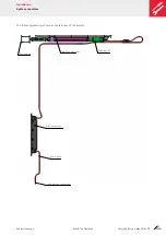
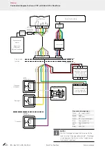
Connection diagram for Eneo C / CC with Roto E-Tec DoorDrive
NOTE!
If a 24 V voltage is applied to terminal 4, the
lock is in the “day operation mode”. If voltage
is not applied, the lock is in the “night opera-
tion mode“ (optional).
1 2 3
1 2 3 4 5 6
1 2 3 4
5
7 91112
7 9
K1b
K1a
IN2
GND
+24V
IN1
N L
N L
–V
+V
+ –
Roto E-Tec DoorDrive
DoorSafe Eneo
Black
Black
Green
On the sash side
Plug-in cable
junction
Inside:
Push-button
Outside:
Push-button
“Close door”
“Day/night”
“Open and
close door”
Switch
On the frame side
Black
box
Access control
system
Finger scan,
Bluetooth,
PIN code keyboard
White
JST plug-
and-socket
connector
Green
Plug-and-
socket
connector
Control unit
Power supply unit for
Roto E-Tec DoorDrive
IN: 100-240 V AC
OUT: 13 V DC/120 W
Eneo power supply unit
IN: 100-240 V AC
OUT: 24 V DC/2.5 A
Two-way intercom system
Signal (e.g. 12 V)
Potential-free contact
Pink
W
hite
Red
Black
Black
Red
Blue
Pink
V
iolet
Yello
w
Green Blue
W
hite
Gre
y
Bro
wn
Bro
wn
Yello
w
Green
Green
Green
Yello
w
Yello
w
Bro
wn
Gre
y
Gre
y
W
hite
Pink
Pink
Red
Black
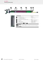
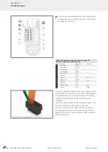
Plug and cable assignment
White:
IN1 / Input 1 (OPEN)
Brown:
+24 V
Green:
GND (24 V)
Yellow:
IN2 / Input 2 (day/night)
Blue:
Close push-button
Violet:
Close push-button
Red:
+13
Black:
GND (13 V)


