70
5.1.3 Graphic Control Panel Overview
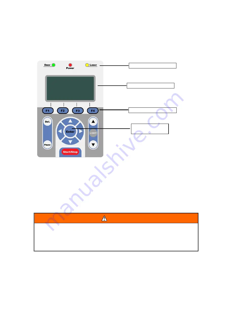
The Control Panel
The control panel on the LV-290 provides an easy access to all the manual controls needed for cutting and
engraving. The liquid crystal display (LCD), functional, directional and selection buttons make navigating through
the machine’s manual controls easy to do.
LED Indicator Lights
The three indicator lights on the LV-290 control panel are part of the system’s safety interlock system.
•
Door – The door light will illuminate when either the top lid or external pass through doors on the LV-
290 are open or improperly closed.
•
Power – The power light will illuminate when the LV-290 is powered on.
• Laser – The laser light will illuminate when the laser is active and in operation.
WARNING
•
DO NOT attempt to remove or modify any component of the safety interlock system.
•
If at any time, any of the access doors are open and the “laser” LED is illuminated, IMMEDIATELY
unplugs the laser system and contact your authorized Roland DG Corporation dealer.
•
DO NOT operate the laser system if any component of the safety system is malfunctioning.
Directional and Selection Buttons
Function (F1 / F2 / F3 / F4)
– Four function buttons allow you to select various functions which will change
depending on what section of the menu you are in. Each function button’s corresponding task will be
displayed right above its respective button on the LCD display screen. Please note that in certain menus, not
every function button will always be mapped to a corresponding action. In these situations, that particular
button will not have a function.
LED Indicator Lights
LCD Display Screen
Function Buttons
Directional and
Selection Buttons
Содержание LV-290
Страница 1: ......
Страница 25: ...23 3 Chapter 3 Mechanical Overview Front View Top View Right View Left View Rear View...
Страница 28: ...26 3 5 Rear View SmartEXTTM Pass Through Door Rear SmartLIDTM Operation Handles Ventilation Openings...
Страница 34: ...32...
Страница 35: ...33...
Страница 36: ...34...
Страница 41: ...39...
Страница 42: ...40...
Страница 50: ...48 3 Click Next 4 The installation would be finished in few seconds...
Страница 74: ...72 5 1 4 Graphic Control Panel Navigation Chart...
Страница 160: ...158 12 Select the converted file and click Open to import the saved file to SmartCONTROLTM 13 File import is completed...
Страница 185: ...183...
Страница 187: ...185...
Страница 193: ...7 Chapter 7 Optional Items Fume Extraction Unit Option Air Compressor Option Items Focus Lens Option...
Страница 199: ...197 Cutting edges achieved with the different lenses...
Страница 211: ...209 9 Chapter 9 Basic Troubleshooting...
Страница 213: ...211 10 Chapter 10 Appendix Glossary Specification Sheet...
Страница 216: ...FA01785 R1 190805...


