


Annexes
R&S
®
CMW500
272
User Manual 1173.9463.02 ─ 02
8.1.2.2
Direct Socket Communication
With direct socket communication the test application communicates directly with the
TCP transport layer, bypassing the presentation and session layer of the OSI reference
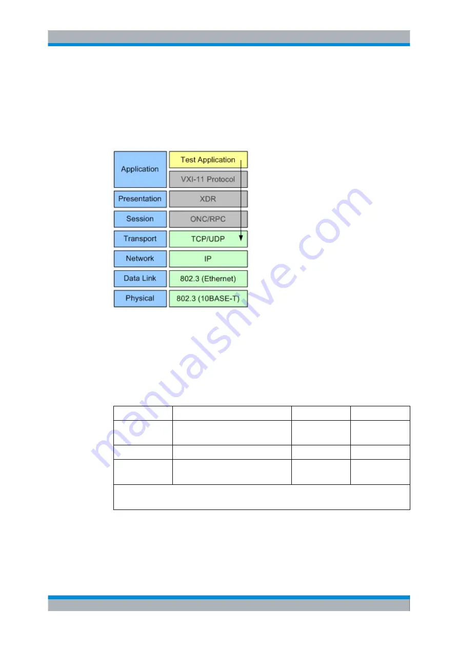
model. The following figure shows an example of the OSI layers used for direct socket
communication. The shown bypassed layers would be used for communication via the
.
Fig. 8-4: Example of OSI layers (socket communication)
Direct socket communication supports the transport of program messages (control com-
mands sent to the instrument) and response messages (returned values received from
the instrument). Service requests and polling are not supported in the raw socket mode.
The additional socket modes "Agilent" and "IEEE1174" are available for compatibility
reasons. The emulation codes for polling, service request and device clear messages
differ for these modes, as listed in the following table. See also:
Table 8-1: Emulation codes supported by the compatibility modes
Purpose
Direction (Controller)
Agilent Codes
IEEE1174 Codes
Poll Status Byte
send
receive
POL\n
POL +stb\n
&POL\cr\n
&stb\cr\n
Service Request
receive
SRQ\n
&SRQ\cr\n
Device Clear
send
receive (DCL complete)
DCL\n
DCL\n
&DCL\cr\n
&DCL\cr\n
\n = newline, CHR$(10)
\cr = carriage return, CHR$(13)
For each socket two ports are defined for communication between instrument and con-
troller. They are called "Data Port" and "Control Port". The ports are used as follows:
●
"Raw" mode uses only the "Data Port". This mode provides the best performance.
Interfaces and Connectors


