Publication 2094-UM001A-EN-P — September 2006
Configure and Startup the Kinetix 6000 Drive System
143
11.
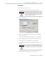
Determine if your test completed successfully.
12.
Repeat Test and Tune the Axes for each axis.
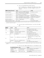
If
Then
Your test completes successfully, this dialog appears.
1. Click OK.
2. Remove the Hardware Enable Input signal (IOD-2)
applied earlier.
3. Go to Step 12.
Your test failed, this dialog appears.
1. Click OK.
2. Make an adjustment to motor velocity.
3. Refer to appropriate Logix motion module setup
and configuration manual for more information.
4. Return to Step 7 and run the test again.
Содержание Allen-Bradley Kinetix 6000
Страница 8: ...Publication 2094 UM001A EN P September 2006 8 Table of Contents...
Страница 18: ...Publication 2094 UM001A EN P September 2006 18 Start...
Страница 118: ...Publication 2094 UM001A EN P September 2006 118 Connecting the Kinetix 6000 Drive System...
Страница 144: ...Publication 2094 UM001A EN P September 2006 144 Configure and Startup the Kinetix 6000 Drive System...
Страница 168: ...Publication 2094 UM001A EN P September 2006 168 Removing and Replacing the Kinetix 6000 Drive Modules...
Страница 190: ...Publication 2094 UM001A EN P September 2006 190 Specifications and Dimensions...
Страница 256: ...Publication 2094 UM001A EN P September 2006 256 Integrating Resistive Brake Modules with Kinetix 6000 Drives...
Страница 265: ...Publication 2094 UM001A EN P September 2006 265 Notes...
Страница 266: ...Publication 2094 UM001A EN P September 2006 266 Notes...
Страница 267: ...Publication 2094 UM001A EN P September 2006 267 Notes...


