Publication 2094-UM001A-EN-P — September 2006
Upgrading Firmware
221
4.
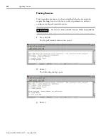
Click Finish. This ControlFLASH warning dialog opens.
5.
Click Yes (only if you are ready).
This ControlFLASH warning dialog opens.
6.
Acknowledge the warning and click OK.
The Progress dialog opens and flashing begins.
The drive module seven-segment LED indicator changes from the
fixed 2, 3, or 4 to F which indicates that flashing is in progress.
After the flash information is sent to the drive, the drive resets and
performs diagnostic checking.
Содержание Allen-Bradley Kinetix 6000
Страница 8: ...Publication 2094 UM001A EN P September 2006 8 Table of Contents...
Страница 18: ...Publication 2094 UM001A EN P September 2006 18 Start...
Страница 118: ...Publication 2094 UM001A EN P September 2006 118 Connecting the Kinetix 6000 Drive System...
Страница 144: ...Publication 2094 UM001A EN P September 2006 144 Configure and Startup the Kinetix 6000 Drive System...
Страница 168: ...Publication 2094 UM001A EN P September 2006 168 Removing and Replacing the Kinetix 6000 Drive Modules...
Страница 190: ...Publication 2094 UM001A EN P September 2006 190 Specifications and Dimensions...
Страница 256: ...Publication 2094 UM001A EN P September 2006 256 Integrating Resistive Brake Modules with Kinetix 6000 Drives...
Страница 265: ...Publication 2094 UM001A EN P September 2006 265 Notes...
Страница 266: ...Publication 2094 UM001A EN P September 2006 266 Notes...
Страница 267: ...Publication 2094 UM001A EN P September 2006 267 Notes...


