Page 22
CABINET HEATER
2.8
Fan Data - High Flow Cabinet Heaters
All COMBAT® High Flow heaters are fitted with three phase motors and belt drive fans to provide a flexible range of fan
performance curves. Table 2.2 shows the standard motor and fans drive arrangement for each model with reference to
the operational fan curve for each model.
The following ten performance graphs (Figs 2.7 to 2.16) show the performance of the fans with two curves. The first
one is
air flow v static pressure
so that an assessment of system performance may be made, the second one is
air flow
v fan motor current
so that a guide to motor performance may be made.
Note:
on some graphs there is a part of the curves that show that when the static pressure is low then the air flow is
high enough to cause a motor current significantly above the full load current recommended by the motor manufacturer.
Operation of the heater in this section of the curve is not recommended, however a 5% overload of the motor is
normally acceptable due to the high air flow over the motor keeping it cool.
It is advised that heaters are selected so that the resultant air flow does not fall below the normal expected air flow as
specified for the similar heat input model of the PGP or POP range as shown in the Data Table 2.1.
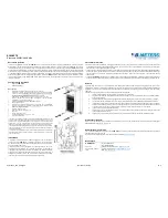
Fig 2.7 Air Flow v Static Pressure & Motor Current - HF30 v4
Air Flow v Static Pressure & Motor Current HF30 v 4
with 2.2 kW motor and 85mm pulley fan pulley 180 mm. Fan 457-486
( Based on Model 30 in 50 cabinet )
0
50
100
150
200
250
300
1.6
1.8
2
2.2
2.4
2.6
2.8
Air Flow m
3
/s
S
tatic P
ressur
e
P
a
3
3.4
3.8
4.2
4.6
5
5.4
M
o
tor Curre
nt Am
ps
Full load cur
re
nt 5.0 A
m
ps
Air flow v Static pressure :
Air flow v Motor current
Graph
HF 11
Содержание Combat HF 30 v4
Страница 2: ......
Страница 47: ...Page 45 CABINET HEATER Section 6 Wiring Diagrams Fig 6 1 As Wired Diagram for Models 015 to 030 Floor Standing ...
Страница 48: ...Page 46 CABINET HEATER Fig 6 2 As Wired Diagram for Models 015 to 030 Horizontal Mounting ...
Страница 49: ...Page 47 CABINET HEATER Fig 6 3 As Wired Diagram for Models 040 and 050 Floor Standing ...
Страница 50: ...Page 48 CABINET HEATER Fig 6 4 As Wired Diagram for Models 040 050 Horizontal Mounting ...
Страница 51: ...Page 49 CABINET HEATER Fig 6 5 As Wired Diagram for Models 060 to 0100 Floor Standing ...
Страница 52: ...Page 50 CABINET HEATER Fig 6 6 As Wired Diagram for Models 060 to 0100 Horizontal Mounting ...
Страница 55: ...Page 55 CABINET HEATER Fig 6 12 Wiring Diagram for High Flow Models HF40 v3 HF50 v2 HF50 v3 and HF50 v4 ...


