background image


GD-70D


- 38 - 


5-3


Turning Off the Detector 


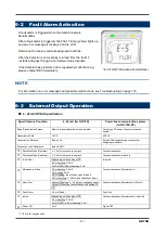
To turn off the detector, open the switch cover on the bottom of the main unit, and turn "OFF" the power 
switch. Then, turn off the power supply (24 VDC) to the detector. 


5-4


Basic Operation 

 
After the warmup procedure, the detector enters detection mode. 


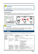
  WARNING 

When the detector is turned off, an alarm may be activated on the upper (central) system. 
Before turning off the detector, the inhibit (point skip) on the upper (central) system must be 
activated. 
Decide whether the power can be turned off by checking the operation of the devices connected to 
the external output or external contact output terminal of the detector. 

If the alarm contact is energized (option), they will activate when the detector is turned "OFF". 

If the detected gas is absorptive, the detector must be flushed thoroughly with fresh air before turning 
"OFF" the detector. 

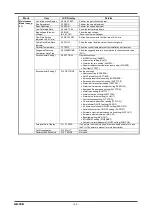
<<Detection Mode>>


PW 

A1 

A2 

LCD 


0.0ppm 

SIH4 


<<User Mode>>


PW 

A1 

A2 

LCD 


1- 1 

ZERO 

MAINTENANCE


<<Maintenance Mode >>


PW 

A1 

A2 

LCD 


2- 0 

GAS TEST 

MAINTENANCE


<<Gas Alarm Test Mode>>


PW 

A1 

A2 

LCD 


0.0ppm 

TEST OFF 

MAINTENANCE


<<Fault Alarm Status>>


PW 

A1 

A2 

LCD 


E-5 

FLOW 


<<Gas Alarm Status>>


PW 

A1 

A2 

LCD 


6.0ppm 

SIH4 


MODE 
(press and hold)


TEST 
(press and hold)


The detector is 
restarted after 
recovering from 
Fault.


MODE 
(press and hold)


PW:POWER 
A1:ALM1 
A2:ALM2 
F:FAULT 

:Lamp on


:Lamp off


Содержание GD-70D Series

Страница 1: ... accordance with the operating manual Regardless of warranty period we shall not make any compensation for accidents and damage caused by using this product The compensation shall be made only under the warranty policy of products or parts replacement Because this is a safety device daily and biannual maintenance must be performed If you find abnormalities in the detector please contact our local ...

Страница 2: ...tor 36 5 3 Turning Off the Detector 38 5 4 Basic Operation 38 5 5 Modes 39 6 Detection Mode 41 6 1 Gas Alarm Activation 41 6 2 Fault Alarm Activation 47 6 3 External Output Operation 47 6 4 Other Functions 50 6 5 About LONWORKS LN specification 53 7 Alarm Test Mode 57 7 1 Alarm Test Mode 57 8 User Mode 59 8 1 User Mode 59 9 Maintenance Mode 65 9 1 Environmental Setting 1 2 9 70 9 2 Alarm Value Set...

Страница 3: ... 12 Product Specifications 119 12 1 Common Specifications 119 12 2 Specifications for Each Model 119 12 3 Specifications for Each Sensor Type 120 12 4 Full Scale and Alarm Points 123 13 Calibration Parts List 126 14 Replacement Parts List 129 Warranty Policy 142 ...

Страница 4: ... quantitative qualitative analysis measurement for gases You must understand the features of the detector before using it so that you can use it properly The detector detects abnormalities in the air caused by the presence of gas or oxygen deficiency with the built in gas sensor unit The concentrations of detected gases are shown on the LCD The built in pump in the detector draws gas to perform ga...

Страница 5: ...handling may cause minor damage on health or assets NOTE This message indicates advice on handling 1 4 Method of confirmation for CE marking type The CE marking is labeled on the detector in case of comply with CE marking Please confirm the instrument specification before using Please refer to the Declaration of Conformity that is at the end of this manual if you have CE marking type You can confi...

Страница 6: ...ay leak from the flow system and pose dangers Be sure that excessive pressure is not applied to the detector when it is used Detected gases must be exhausted from the outlet GAS OUT on the bottom of the detector to a safe place using an exhaust tube Handling the sensor unit Do not disassemble the electrochemical type sensor unit ESU or galvanic cell type sensor unit OSU because they contain electr...

Страница 7: ...formed inside the tube causes clogging or gas absorption which disturbs accurate gas detection Thus condensation must be avoided In addition to the installation environment carefully monitor the temperature humidity of the sampled area to prevent condensation inside the tube In particular when detecting a corrosive water soluble gas such as a strong acid gas the gas is undetectable and furthermore...

Страница 8: ...ard Accessories Main Unit Standard Accessories Operating manual Protective rubber cap to be removed when using the detector Dedicated handling lever for wiring Dust filter Interference gas removal filter to be supplied with sensor units for certain gases ...

Страница 9: ...For more information on the pyrolyzer unit PLU 70 see the separate operating manual 3 2 Outline Drawing Pyrolyzer Unit Unit mm M5 mounting hole GAS IN GAS OUT Sensor unit display Operating switch Display Protective cover for power switch Screw for grounding earth rod External wire hole Connector for PLU Connector for PoE Power switch ...

Страница 10: ...r lamp First alarm lamp Second alarm lamp Fault lamp Gas name display Concentration value display Unit display Concentration bar indicator Alarm setpoint indicator Flow rate indicator Communication indicator Maintenance indicator Inhibit indicator Pyrolyzer unit connection indicator CAUTION Each unit consists of precision parts When a unit is detached be careful not to drop it Dropping the unit co...

Страница 11: ...lays the unit according to the specification ppm ppb vol LEL Concentration bar indicator The detectable range full scale FS is divided into 20 segments The increase in concentration is displayed in proportion to the full scale Alarm setpoint indicator The alarm setpoints AL1 and AL2 are indicated on the concentration bar Flow rate indicator Displays the flow rate When the line is in the middle of ...

Страница 12: ...correct sensor unit After the sensor unit is replaced always perform a gas calibration zero adjustment and span adjustment Mounting Plate The mounting plate gets installed to the installation site The main unit connects to the mounting plate using the 10 point terminal plate Sensor Unit A sensor unit installed in the detector is the same regardless of the detection principle which means sensor uni...

Страница 13: ...unit must be put into the dedicated case specified by us and stored away from direct sunlight in a clean place where the temperature and humidity are maintained at a normal level and where appropriate measures are taken to prevent the sensor from being taken out easily When the sensor unit is transported out of your factory please use a transportation company which can handle specified designing c...

Страница 14: ...POWER INPUT 24 VDC Power supply part Gas alarm contact ALM1 ALM2 Fault alarm contact FAULT Standard setting of contact activation De energized De energized at a normal state ON ALARM Closed contact at an alarm state Alarm contact controller Transmitter 4 20 mA NT EA specification Pump control circuit Amplifier Controller CPU Display POWER ALM1 ALM2 FAULT LCD Operating unit MODE TEST SET 4 20 mA sp...

Страница 15: ... 15 GD 70D Tubing Diagram ...

Страница 16: ...may damage the detector resulting in inaccurate gas detection 4 2 Precautions for installation sites Do not install the detector in a place with vibrations or shocks The detector contains sensitive electronic parts The detector must be installed in a stable place without vibrations or shocks and where it will not fall Do not install the detector in a place exposed to water oil or chemicals Avoid i...

Страница 17: ...e detector cannot be performed or where handling the detector involves dangers Regular maintenance of the detector must be performed Do not install the detector in a place where the equipment must be stopped when maintenance is performed where parts of the equipment must be removed to perform maintenance or where the detector cannot be removed because tubes or racks prevent access to it Do not ins...

Страница 18: ...m outside the factory plant lightning will cause problems Because lightning acts as a large emission source while cables act as a receiving antenna devices connected to the cables may be damaged Lightning cannot be prevented Cables installed in a metal conduit or under the ground cannot be completely protected from a power surge caused by lightning Although complete elimination of disasters caused...

Страница 19: ...addition the surge absorbing part SK2 must be attached to the loaded side of the external relay if necessary It may be recommended that the surge absorbing part be attached to the contact for certain load conditions It must be attached to an appropriate position by checking how the load is activated GD 70D SK1 SK2 Alarm Contact Power supply Power supply External relay low voltage relay SK1 SK2 Sur...

Страница 20: ...CAUTION Multiple detectors installed in the same location must be installed at least 5 mm apart It is recommended that they be 10mm apart When you install more than one detector in the same location install them in a rack or on a wall that is not affected by vibrations When the detectors are installed side by side if the rack or wall in which the detectors are installed does not have enough streng...

Страница 21: ...le pushing the lever as shown to the right Do not rotate or move the flathead screwdriver Simply insert it into the mounting plate 4 Remove the silver mounting plate from the back of the GD 70D CAUTION The detector must be installed in the correct orientation to ensure its performance Install the detector as shown on the following example The detector must also remain in this orientation during tr...

Страница 22: ... type DC power line communication system NT specification Shielded twisted pair cable of KPEV S etc 1 25 mm2 1P For Ethernet EA Power Cable of CVV etc 1 25 mm2 2 core Signal Ethernet cable category 5 or higher For PoE EA Ethernet cable category 5 or higher For LONWORKS output cable Shielded twisted pair cable of KPEV S etc 1 25 mm2 1P For contact Cable of CVV etc 1 25mm2 max 6 core CAUTION Be care...

Страница 23: ...vailable Bar terminal ferrule Model 216 Series manufactured by WAGO Crimping tool Model VarioCrimp 4 206 204 manufactured by WAGO Dedicated handling lever CAUTION A bar terminal of the specified model must be used Using other bar terminals invalidates the guarantee of the performance Wiring hole Driver slot Conductive part Cage clamp spring Top handling slot CAUTION The specified bare wire length ...

Страница 24: ...open For the NT specification terminals 3 and 4 are not used For the EA specification with PoE connection terminals 1 and 2 are disabled 1 Make sure power to the detector is turned off 2 While pushing the blue lever toward the mounting plate push the main unit up 3 If you cannot move the main unit insert a larger flathead screwdriver into the mounting plate while pushing the lever as shown to the ...

Страница 25: ...iring hole If you are not using the handling lever push down into the top handling slot with a flathead screwdriver 8 Hold the lever down while you insert a wire into the wiring hole 9 Release the lever Gently pull on the inserted wire to make sure it is connected 10 Repeat for all other wiring connections Push the dedicated handling lever to open the terminals Insert 1 wire per terminal Push the ...

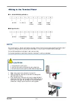
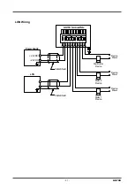
Страница 26: ...ring ALM2 FAULT 3 4 5 6 7 8 9 10 ALM1 4 20mA Device Power Device Power Alarm 1 Device Alarm 2 Device Fault Alarm Device 24VDC Controller orRecording Device 1 DCGround 4 20mA In FB GD 70DTerminalPlate DC24V 2 CableShield Device Power ...

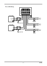
Страница 27: ... Wiring FAULT 3 4 5 6 7 8 9 10 ALM1 4 20mA ALM2 Device Power Device Power Alarm 1 Device Alarm 2 Device Fault Alarm Device Power Supply 1 24VDC 24VDC Device Power PLCorDCS CableShield CableShield GD 70DTerminalPlate DC24V 2 ...

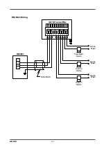
Страница 28: ... 28 RM 5003 Wiring FAULT ALM2 4 20mA ALM1 10 9 8 7 6 5 4 3 Fault Alarm Device Alarm 2 Device Alarm 1 Device Device Power Device Power 13 14 12 1 Device Power 11 RM 5003 CableShield 2 DC24V GD 70DTerminalPlate ...

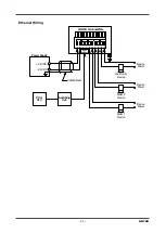
Страница 29: ...6 5 4 3 FAULT ALM2 4 20mA ALM1 24VDC Fault Alarm Device Alarm 2 Device Alarm 1 Device Device Power Device Power RJ45 Connector 10 9 8 Switching Hub PCor PLC 1 Power Supply Device Power 24VDC 2 DC24V GD 70DTerminalPlate CableShield ...

Страница 30: ...ng 9 10 ALM1 4 20mA ALM2 FAULT 3 4 5 6 7 8 1 Device Power Device Power Alarm 1 Device Alarm 2 Device Fault Alarm Device PCor PLC SwitchingHub withPoE Functionality RJ45 Connector GD 70DTerminalPlate DC24V 2 Device Power ...

Страница 31: ...ring FAULT ALM2 ALM1 Device Power LON WORKS 10 9 8 7 6 5 4 3 Power Supply 24VDC Fault Alarm Device Alarm 2 Device Alarm 1 Device Device Power 1 Device Power LON 24VDC 2 DC24V GD 70DTerminalPlate CableShield CableShield ...

Страница 32: ...ghten the zip tie to secure the wires NOTE When an optional cable gland is used it must be attached to the external wiring hole 3 4 5 6 7 8 9 10 ALM1 4 20mA ALM2 FAULT Device Power Alarm 1 Device Alarm 2 Device Fault Alarm Device 1 Device Power BlockingFilter B F Power Supply 24VDC DC 24V DC 24V Upper Unit RM 70NT GD 70D NT TerminalPlate DC24V 2 CableShield Device Power Position the band so that i...

Страница 33: ...ting plate is above the main unit as viewed from front If it is not push the main unit down farther WARNING Before turning on the detector do not forget to connect it to a grounding circuit For stable operation of the detector and safety it must be connected to a grounding circuit Do not connect the grounding wire to a gas pipe The grounding must be made as D type grounding below 100 Ω of groundin...

Страница 34: ... short piece of 4 mm x 6 mm Teflon tubing to the GAS IN fitting as shown below Be sure the tubing insert ferrule and nut are installed properly 3 Connect the dust filter to the tubing 4 Install another piece of 4 mm x 6 mm Teflon tubing to the other end of the dust filter and route it to the sample area 5 Attach 4 mm x 6 mm Teflon tubing to the GAS OUT fitting and route it to a safe area Be sure t...

Страница 35: ...h the liquid If any liquid leaks while the sensor unit is installed in the detector turn off power to the detector and contact RKI immediately Because the pyrolysis particle type sensor unit SSU contains a small amount of radioactive materials it must be transported appropriately as a L type package When the sensor unit is returned to us it must be handled by a transportation company which can han...

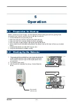
Страница 36: ...e see Specifications Alarm contacts may be activated during startup Take steps to ensure this does not have any unwanted effects Verify that the GAS IN and GAS OUT lines are clear Verify that the dust filter is installed correctly 5 2 Starting Up the Detector 1 The power switch is protected by a cover to prevent accidental access Rotate the switch cover to gain access to the power switch Return th...

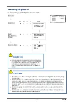
Страница 37: ...ading the sensor memory during the initial clear If a new sensor unit is installed or the sensor unit is replaced after the detector is started the sensor unit must be warmed up for a specified period which is determined depending on the type of the sensor unit Suggested warm up time for SGU type sensor units is displayed in Maintenance Mode During the warm up the alarm activation and output signa...

Страница 38: ...ces connected to the external output or external contact output terminal of the detector If the alarm contact is energized option they will activate when the detector is turned OFF If the detected gas is absorptive the detector must be flushed thoroughly with fresh air before turning OFF the detector Detection Mode PW A1 A2 F LCD 0 0ppm SIH4 User Mode PW A1 A2 F LCD 1 1 ZERO MAINTENANCE Maintenanc...

Страница 39: ...ow the setting of typical menus First alarm setpoint AL1 Second alarm setpoint AL2 Alarm delay time Zero suppression value Zero follower ON OFF Sensitivity correction ON OFF Flow Rate Indicator 1 3 FLOW Show the current flow rate Address Display 1 4 ADDRESS Show the address Detector Version Display 1 5 70D VER Show the program version of the main unit Unit Version Display 1 6 UNIT VER Show the pro...

Страница 40: ... setting ALM DLY Regular replacement operation pump stop MAINTE Fault test F TEST Environmental Setting 2 2 10 SETTING2 Function settings Address setting ADDRESS Date Time setting DAY TIME Zero suppression value setting SUPPRESS Zero suppression system setting SUP TYPE Alarm test time contact setting TEST RLY Alarm test time external output setting TEST4 20 Energized De energized setting RLY PTRN ...

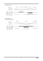
Страница 41: ...dard 2 seconds is enabled in the detector to prevent a false activation It can be disabled if desired Display Operation During Alarm Condition Gas Concentration Display The gas concentration is displayed on the LCD If the concentration is above the detection range over scale is displayed on the LCD instead of the gas concentration Alarm Indicator Lamp ALM1 Red ALM2 Red When the first alarm setpoin...

Страница 42: ...below the alarm setpoint Contact Activation Auto reset In case of Auto reset setting the contact is activated when the gas concentration reaches or exceeds the alarm setpoint value The contact activation is reset automatically when the gas concentration drops below the alarm setpoint value NOTE In DETECTION MODE select and press one of the following key to reset MODE or TEST SET Alarm Pattern H HH...

Страница 43: ... 43 GD 70D Alarm Pattern L H Alarm Pattern L LL oxygen deficiency alarm ...

Страница 44: ...ontact is activated when the gas concentration reaches or exceeds the alarm setpoint value The alarm indication lamp blinks during warning It changes to a light after reset is performed It turns off when the gas concentration drops below the alarm set point value Alarm Pattern H HH ...

Страница 45: ... 45 GD 70D Alarm Pattern L H ...

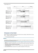
Страница 46: ... time you get to the instrument to check it 2 Based on your company s safety practices no one can be allowed to access the monitored zone to ensure safety 3 If the detector display is still indicating the presence of gas close the area s main gas valve and then verify that the detector s gas concentration reading dropped 4 While wearing protective equipment in case gas is still present use a porta...

Страница 47: ...unication system Transmission Path CVVS KPEV S Transmission Distance Below 1 km Below 300 m depending on the system designing conditions Connection Load Resistance Below 300 Ω Detection Mode No Alarm 4 20 mA concentration output Concentration data Detection Mode Gas Alarm 4 20 mA concentration output Concentration data Alarm bits Initial Clear Depending on the setting of 2 5 mA setting 2 5 mA 4 mA...

Страница 48: ...rmup for oxygen units Understand how the detector functions and take actions to prepare for false alarms Special Cases Maintenance output setting Sensor unit Details 2 5 mA Use OSU L LL L H Output 2 5 mA during maintenance or inhibit Possibility of false alarm in the upper unit L alarm 4 mA HOLD 4 20 mA Specification change To OSU 0 25 vol When changing from a H HH alarm pattern to an L LL or L H ...

Страница 49: ...SNTP receiving time information from a time server can correct the clock at regular intervals Modbus slave function Modbus TCP Works as a Modbus slave and feeds back a setting value in response to a read request or changes a setting value in response to a write request PLC linkage function FINS MC Sends a setting value to PLC to provide information to be processed by PLC in a ladder program Readin...

Страница 50: ...20 9 for oxygen until the reading exceeds the set suppression value The factory setting for the suppression function is OFF for every gas type except for oxygen Example SiH4 0 15 ppm range 0 5ppm SIH4 Suppression Disabled A variation around zero is displayed as the reading 0 0ppm SIH4 Suppression Enabled A variation under the set suppression value ie 6 of full scale or 0 9 ppm for SiH4 is shown as...

Страница 51: ...n of the sensor CAUTION The sensitivity correction is just an auxiliary function It uniformly lifts the span up based on the sensor s degradation pattern only Sensitivity correction cannot consider the sensitivity variation of an individual sensor To correct the sensitivity variation you must regularly calibrate the sensor The zero drift is periodically corrected to bring the reading back to zero ...

Страница 52: ... SPEC MAINTENANCE Specification Change Displayed when a unit with a different specification principle type range and so on from the previous one is attached 1 Press the MODE key to confirm the new specification and start the monitor If you did not install a sensor unit with a different specification this message might mean there is an installation error Check the sensor installation CAUTION If you...

Страница 53: ...he zero adjustment 1 1 ZERO MAINTENANCE SET Zero Adjustment P51 To reissue the neuron ID please press the MODE key in user mode for 3 seconds return to the detection mode and enter the user mode again WARNING When adjustment is completed press the MODE key and be sure to return to detection mode When left in user mode it automatically returns to detection mode after 10 hours ...

Страница 54: ...ch nvoFaultS SNVT_switch nvoGasName SNVT_str_asc nvoHertBeat SNVT_state nviComand SNVT_str_asc nvoComand SNVT_str_asc nviReset SNVT_lev_disc Virtual Function Block nciMinSendTM SNVT_time_sec nciMaxSendTM SNVT_time_sec nciMinSendTl SNVT_time_sec nciMaxSendTl SNVT_time_sec nciMaxSendHB SNVT_time_sec Mandato ry Implementation Specific ...

Страница 55: ...ec has not elapsed since last transmission wait until Bsec has elapsed before sending it even if VAL is updated NO Variable name Variable type Contents 1 nvoConc SNVT_ppm_f It is the same as the current density output Floating point of 16 BIT synchronizes with the display of the detection part 2 nvoNstate SNVT_state It is the same as the current density output Status of 16 BIT expresses measuremen...

Страница 56: ...6 don t transmit every Asec It outputs to nvoComand 14 for input data of nviComand 13 nviComand 13 A1 R nvoComand 14 A1 R express 1st alarm point read value in hexadecimal nviComand 13 A2 R nvoComand 14 A2 R express 2nd alarm point read value in hexadecimal nviComand 13 AD R nvoComand 14 AD R express Alarm delay time mesc 10 units read value in hexadecimal ...

Страница 57: ... TEST RLY menu item in Maintenance Mode Increase or decrease the reading by pressing the or key 0 0ppm TEST OFF MAINTENANCE First Alarm When the reading reaches the first alarm the ALM1 lamp lights up When TEST RLY is set to ON the first alarm contact is activated 5 0ppm TEST OFF MAINTENANCE Second Alarm When the reading reaches the second alarm the ALM2 lamp lights up When TEST RLY is set to ON t...

Страница 58: ...GD 70D 58 Return to Detection Mode Press the TEST key for 3 seconds ...

Страница 59: ...Zero Adjustment P62 1 2 CONFIRM Show the typical setpoint 1 2 CONFIRM MAINTENANCE SET Setpoint Display P63 1 3 FLOW Show the current flow rate 1 3 FLOW MAINTENANCE SET 0 50 L M MAINTENANCE 1 4 ADDRESS Show the address for GD 70D NT 1 4 ADDRESS MAINTENANCE SET 01 ADDRESS MAINTENANCE WARNING After the adjustment is completed do not forget to press the MODE key to return to Detection Mode ...

Страница 60: ...CE 1 8 M MODE Enter Maintenance Mode 1 8 M MODE MAINTENANCE SET See Maintenance Mode on page 65 To 1 1 ZERO In case of GD 70D EA 1 7 NET VER Show the program version of the communication function NT specification 1 7 NET VER MAINTENANCE SET 01234 MAINTENANCE 1 8 COM SET Set communication output Press the or key to select the communication output and then press the SET key to confirm the value 1 8 ...

Страница 61: ...e 65 To 1 1 ZERO NOTE Communication output setting 1 8 COM SET is displayed only for EA specification In EA specification if only analog transmission is used Ethernet is not used if the communication output setting is set to A Communication Abnormalities E 6 does not occur even if an Ethernet cable is not connected ...

Страница 62: ... the reading is 20 9 vol For information on the span adjustment see Maintenance on page 86 Zero Adjustment PW A1 A2 F LCD From Detection Mode press the MODE key for three seconds 0 0ppm SIH4 1 1 ZERO Press the SET key 1 1 ZERO MAINTENANCE Current Concentration Value Display Press the SET key to perform the zero adjustment 1 1ppm ZERO SET MAINTENANCE Zero Adjustment Completed The menu returns to 1 ...

Страница 63: ...y for three seconds 0 0ppm SIH4 1 1 ZERO Press the key 1 1 ZERO MAINTENANCE 1 2 CONFIRM Press the SET key 1 2 CONFIRM MAINTENANCE First Alarm Setpoint 5 0ppm AL 1 MAINTENANCE Second Alarm Setpoint 10 0ppm AL 2 MAINTENANCE Alarm Delay Time seconds 2 ALM DLY MAINTENANCE Zero Suppression Value 0 9ppm SUPPRESS MAINTENANCE Zero Follower ON OFF If ESU or SSU sensor installed ON ZERO F MAINTENANCE ...

Страница 64: ...GD 70D 64 Sensitivity Correction ON OFF If ESU sensor installed OFF S ASSIST MAINTENANCE To First Alarm Setpoint Indicator ...

Страница 65: ...e flow sensor with the flow rate at 0 5 L min Pump Ratio Flow Rate Indicator P110 2 6 FLOW Show the output and flow rate of the current pump Detector Temperature 2 7 TEMP Show the current temperature of the installation environment Suggested Warm up Completion Date Time 2 8 WARMTIME Show the suggested warm up completion for SGU type sensors Environmental Setting 1 P70 2 9 SETTING1 Operation settin...

Страница 66: ...imiter setting AL LIMIT Fault activation setting FLT PTRN Flow rate auto adjustment setting AT FLOW Zero follower ON OFF setting ZERO F 24 hours zero follower ON OFF setting ZERO 24F Sensitivity correction ON OFF setting S ASSIST External output in maintenance mode setting MNT OUT External output adjustment MA 4 20 Backlight setting BK LIGHT ETHERNET setting ETHERNET Pump drive level diagnosis ON ...

Страница 67: ...he SET key again for three seconds M MODE MAINTENANCE Maintenance Mode 2 0 GAS TEST Perform a test with the gas The reading changes and the alarm lamp lights up but the alarm contacts are not activated and the 4 20 mA output does not track the changes 2 0 GAS TEST MAINTENANCE SET 0 2ppm GAS TEST MAINTENANCE Alternate Display 0 2ppm SIH4 MAINTENANCE 2 1 ZERO Perform a zero adjustment 2 1 ZERO MAINT...

Страница 68: ... at other than the specified flow rate gases cannot be detected properly due to an incorrect flow rate Press the MODE key to cancel this menu 2 5 DEF FLOW MAINTENANCE SET 1000 DEF FLOW MAINTENANCE 2 6 FLOW Show the output and flow rate of the current pump 2 6 FLOW MAINTENANCE SET 50 0 50 L M MAINTENANCE 2 7 TEMP Show the temperature of the detector 2 7 TEMP MAINTENANCE SET 25 0 C TEMP MAINTENANCE ...

Страница 69: ...zer unit PLU 70 is used 2 11 PL DATA MAINTENANCE SET For information on Pyrolyzer Data Display see PLU 70 Operating Manual 2 12 FAULT This is used by the manufacturer to investigate and analyze the causes of faults This is not used by the user 2 12 FAULT MAINTENANCE 2 13 F MODE Changes to the factory mode This is not used by the user 2 13 F MODE MAINTENANCE To 2 0 GAS TEST ...

Страница 70: ...T key 1 8 M MODE MAINTENANCE Then press and hold the SET key again for three seconds M MODE MAINTENANCE 2 0 GAS TEST The first item in Maintenance Mode will display 2 0 GAS TEST MAINTENANCE 2 9 SETTING1 Press the key until the SETTING1 screen displays Press the SET key 2 9 SETTING1 MAINTENANCE SET 0 INHIBIT Select either ON or OFF and then press the SET key to confirm the selection When ON is sele...

Страница 71: ...he pump You can also press the MODE key to exit this menu and restart the pump SET 3 MAINTE MAINTENANCE SET MAINTE MAINTENANCE Pump Stop Drive Sound Stop SET 4 F TEST Perform a fault alarm test SET 4 F TEST MAINTENANCE SET Fault Alarm Test P73 To SET 0 INHIBIT Setting 9 2 Alarm Value Setting 2 9 SET 1 Alarm Value Setting PW A1 A2 F LCD From Detection Mode press and hold the MODE key for three seco...

Страница 72: ... ALM P Press the key until the ALM P screen displays SET 1 ALM P MAINTENANCE SET 1 ALM P Press the SET key SET 1 ALM P MAINTENANCE First Alarm Value Setting Use the or key to change the setpoint Press the SET key to confirm the value Press the MODE key to skip this menu 5 0ppm AL 1 MAINTENANCE Second Alarm Value Setting Use the or key to change the setpoint Press the SET key to confirm the value P...

Страница 73: ...NTENANCE User Mode In 1 8 M MODE press the SET key 1 8 M MODE MAINTENANCE Then press and hold the SET key again for three seconds M MODE MAINTENANCE 2 0 GAS TEST The first item in Maintenance Mode will display 2 0 GAS TEST MAINTENANCE 2 9 SETTING1 Press the key until the SETTING1 screen displays Press the SET key 2 9 SETTING1 MAINTENANCE SET 1 ALM P Press the key until the F TEST screen displays S...

Страница 74: ...Setting 2 menu are factory set and do not normally need to be changed Be careful not to change these settings by mistake Environmental Setting 2 PW A1 A2 F LCD From Detection Mode press and hold the MODE key for three seconds 0 0ppm SIH4 1 8 M MODE Press the key until the Maintenance Mode screen displays For GD 70D EA units the Maintenance Mode screen is item 1 9 1 8 M MODE MAINTENANCE User Mode I...

Страница 75: ...the SET key to confirm the value SET 2 SUPPRESS MAINTENANCE SET 0 9ppm SUPPRESS MAINTENANCE SET 3 SUP TYPE Set the suppression system Select either CUT or SLOPE and then press the SET key to confirm the selection When CUT is selected the display will jump up to the gas reading as soon as it exceeds the suppression value When SLOPE is selected the display will ramp up to the gas reading once it exc...

Страница 76: ...ET 6 RLY PTRN MAINTENANCE SET Energized De Energized Contact Setting P81 SET 7 ALM TYPE Set the alarm type When the galvanic cell type OSU is installed you can select either L LL both alarms decreasing L H alarm 1 decreasing alarm 2 increasing or H HH both alarms increasing SET 7 ALM TYPE MAINTENANCE SET L LL ALM TYPE MAINTENANCE L H ALM TYPE MAINTENANCE H HH ALM TYPE MAINTENANCE SET 8 ALM PTRN Th...

Страница 77: ... Select either ON or OFF and then press the SET key to confirm the selection When ON is selected the zero follower function is activated When SSU is installed you must select ON SET 12 ZERO F MAINTENANCE SET ON ZERO F MAINTENANCE OFF ZERO F MAINTENANCE SET 13 ZERO 24F This is a supplemental setting screen for the above zero follower function A setting to determine whether the first 24 hour zero fo...

Страница 78: ... to the upper unit or the ammeter After adjustment of 4 mA is completed perform the adjustment of 20 mA Press the MODE key to exit menu after entering SET 16 MA 4 20 MAINTENANCE SET 100 4MA ADJ MAINTENANCE 100 20MA ADJ MAINTENANCE SET 17 BK LIGHT Set the backlight Select either ON or SAVE and then press the SET key to confirm the selection When ON is selected the backlight is on continuously When ...

Страница 79: ...te Time Setting 2 10 SET 1 Date Time Setting PW A1 A2 F LCD From Detection Mode press and hold the MODE key for three seconds 0 0ppm SIH4 1 8 M MODE Press the key until the Maintenance Mode screen displays For GD 70D EA units the Maintenance Mode screen is item 1 9 1 8 M MODE MAINTENANCE User Mode In 1 8 M MODE press the SET key 1 8 M MODE MAINTENANCE Then press and hold the SET key again for thre...

Страница 80: ...m the value 12 00 2009 01 01 MAINTENANCE Date Setting Select the number by pressing the or key and then press the SET key to confirm the value 12 00 2009 01 01 MAINTENANCE Hour Setting Select the number by pressing the or key and then press the SET key to confirm the value 12 00 2009 01 01 MAINTENANCE Minute Setting Select the number by pressing the or key and then press the SET key to confirm the...

Страница 81: ...E MAINTENANCE User Mode In 1 8 M MODE press the SET key 1 8 M MODE MAINTENANCE Then press and hold the SET key again for three seconds M MODE MAINTENANCE 2 0 GAS TEST The first item in Maintenance Mode will display 2 0 GAS TEST MAINTENANCE 2 10 SETTING2 Press the key until the SETTING2 screen displays Press the SET key 2 10 SETTING2 MAINTENANCE SET 6 RLY PTRN Press the key until the RLY PTRN scree...

Страница 82: ...INTENANCE Return to SET 6 RLY PTRN NOTE When De energized nd is selected the relay is energized and activated during an alarm condition de energized during normal operation When the alarm contacts are configured as normally open the contacts are open during normal operation and closed during an alarm condition When the alarm contacts are configured as normally closed the contacts are closed during...

Страница 83: ...MAINTENANCE User Mode In 1 8 M MODE press the SET key 1 8 M MODE MAINTENANCE Then press and hold the SET key again for three seconds M MODE MAINTENANCE 2 0 GAS TEST The first item in Maintenance Mode will display 2 0 GAS TEST MAINTENANCE 2 10 SETTING2 Press the key until the SETTING2 screen displays Press the SET key 2 10 SETTING2 MAINTENANCE SET 18 RLY PTRN Press the key until the ETHERNET screen...

Страница 84: ... in the same way 0 IP 1 MAINTENANCE SET 255 IP 1 MAINTENANCE IP2 IP4 Subnet Mask Setting Change the value by pressing the or key and then press the SET key to confirm the value There are subnet masks from SUB1 to SUB4 Select one using and keys and set them one by one in the same way 0 SUB 1 MAINTENANCE SET 255 SUB 1 MAINTENANCE SUB2 SUB4 Default Gateway Setting Change the value by pressing the or ...

Страница 85: ...A MAINTENANCE SET 15 PLC AREA MAINTENANCE Setting Result Record To record the results of the settings made in the above press the SET key SAVE MAINTENANCE SET SPAN Y N MAINTENANCE MAC Address Check Press the SET key to record the setting results and return to SET 18 ETHERNET In ETHERNET mode it is necessary to record setting results after all the settings have been selected Press the MODE key befo...

Страница 86: ...If the reading is not zero or 20 9 vol perform a zero adjustment Flow rate check See the flow rate indicator to check for abnormalities Filter check Check the dust filter for dust or clogging Alarm test Inspect the alarm circuit by using the alarm test function Span adjustment Perform a span adjustment using calibration gas Gas alarm check Check alarm operation using calibration gas 10 2 Calibrati...

Страница 87: ...ane 0 2 000 ppm Calibrating with on page 90 CH2Cl2 Dichloromethane 0 2 000 ppm Calibrating with a Humidifier MOS Sensors on page 103 CH3CN Acetonitrile 0 2 000 ppm Calibrating with a Humidifier MOS Sensors on page 103 CH3COOH Acetic acid 0 30 0 ppm Calibrating with a Surrogate Gas Sensors with Factors on page 93 CH3NH2 Methylamine 0 15 0 ppm Calibrating with a Surrogate Gas Sensors with Factors on...

Страница 88: ... HCl on page 99 H2O2 Hydrogen peroxide 0 3 00 ppm Calibrating with a Surrogate Gas Sensors with Factors on page 93 H2S Hydrogen sulfide 0 1 00 ppm Calibrating with a Demand Flow Regulator on page 90 0 30 0 ppm H2Se Hydrogen selenide 0 0 20 ppm Calibrating with a Surrogate Gas Sensors with Factors on page 93 H9NSi3 Trisilylamine 0 15 0 ppm Calibrating with a Surrogate Gas Sensors with Factors on pa...

Страница 89: ...h a Surrogate Gas Sensors with Factors on page 93 0 1 00 ppm PH3 Phosphine 0 1 00 ppm Calibrating with a Demand Flow Regulator on page 90 R32 Difluoromethane 0 2 000 ppm Calibrating with a Humidifier MOS Sensors on page 103 0 5 000 ppm 0 9 000 ppm R41 Fluoromethane 0 2 000 ppm Calibrating with a Humidifier MOS Sensors on page 103 TEOS Tetraethyl orthosilicate 0 15 0 ppm Calibrating a Pyrolyzer Uni...

Страница 90: ... 3 hours 0 30 0 ppm Hydrogen sulfide H2S 15 ppm 3 hours HCN Hydrogen cyanide 0 9 15 0 ppm Hydrogen cyanide HCN 10 ppm 3 hours N2O Nitrous oxide 0 500 ppm Nitrous oxide NO 250 ppm 1 hour NH3 Ammonia 0 75 0 ppm Ammonia NH3 50 ppm 3 hours NO Nitric oxide 0 100 ppm Nitric oxide NO 25 ppm 3 hours NO2 Nitrogen dioxide 0 9 00 ppm Nitrogen dioxide NO2 5 ppm 6 hours 0 15 0 ppm Nitrogen dioxide NO2 10 ppm 6...

Страница 91: ...nds M MODE MAINTENANCE 2 0 GAS TEST The first item in Maintenance Mode will display 2 0 GAS TEST MAINTENANCE Performing a Zero Adjustment 2 1 ZERO Press the key until the ZERO screen displays Press the SET key 2 1 ZERO MAINTENANCE Current Concentration Value Display Press the SET key to perform the zero adjustment 1 1ppm ZERO SET MAINTENANCE Zero Adjustment Completed The instrument will indicate w...

Страница 92: ...AN GAS MAINTENANCE Disconnect Gas Disconnect the calibration tubing from the tubing stub on the GAS IN fitting Span Adjustment Using the or keys adjust the reading to match the concentration listed on your calibration cylinder Press the SET key 8 0ppm SPAN VAL MAINTENANCE Span Adjustment Completed The instrument will indicate whether the span adjustment passed OK or failed NG 8 0ppm SPAN OK MAINTE...

Страница 93: ...rtiary butyl amino silane 0 15 0 ppm Ammonia NH3 5 ppm 6 hours CH3COOH Acetic acid 0 30 0 ppm Chlorine Cl2 2 ppm 3 hours CH3NH2 Methylamine 0 15 0 ppm Ammonia NH3 5 ppm 6 hours CH6Si Methylsilane 0 20 0 ppm Silane SiH4 5 ppm 3 hours ClF3 Chlorine trifluoride 0 0 60 ppm Chlorine Cl2 2 ppm 3 hours COF2 Cobalt difluorine 0 6 00 ppm Chlorine Cl2 2 ppm 3 hours DEA Diethylamine 0 15 0 ppm Ammonia NH3 5 ...

Страница 94: ...as close to 50 of full scale as possible It is not necessary to dilute these gases to achieve that goal The concentration listed on the calibration cylinder multiplied by the factor listed on the sensor should be as close to 50 of full scale as possible but any value between 10 and 100 of full scale can be used to calibrate Calibration Equipment for Gases Needing Dilution 0 5 LPM fixed flow regula...

Страница 95: ...n Total Parts in Gas Bag from discussion in previous section Gas Flow Time Nitrogen Flow Time 2 1 part gas 1 part N2 1 minute 1 minute 3 1 part gas 2 parts N2 1 minute 2 minutes 4 1 part gas 3 parts N2 45 seconds 2 minutes 15 seconds 5 1 part gas 4 parts N2 30 seconds 2 minutes 6 1 part gas 5 parts N2 20 seconds 1 minute 40 seconds 7 1 part gas 6 parts N2 20 seconds 2 minutes 8 1 part gas 7 parts ...

Страница 96: ...e Mode From Detection Mode press and hold the MODE key for three seconds 0 0ppm SIH4 1 8 M MODE Press the key until the Maintenance Mode screen displays For GD 70D EA units the Maintenance Mode screen is item 1 9 1 8 M MODE MAINTENANCE User Mode In 1 8 M MODE press the SET key 1 8 M MODE MAINTENANCE Then press and hold the SET key again for three seconds M MODE MAINTENANCE 2 0 GAS TEST The first i...

Страница 97: ... Connect Gas Open the hose clamp on the gas bag and immediately connect the tubing to the tubing stub on the GAS IN fitting OR Use the calibration tubing to connect the demand flow regulator to the tubing stub on the GAS IN fitting Allow gas to flow for 2 minutes Accept Reading Press the SET key when the reading has stabilized The reading must be above 10 of the full scale value in order to contin...

Страница 98: ...ailed NG 8 0ppm SPAN OK MAINTENANCE OR 8 0ppm SPAN NG MAINTENANCE Return to 2 2 SPAN Save Adjustment To save the adjustment result press the SET key Press the MODE key to cancel this menu 8 0ppm SPAN Y N MAINTENANCE Adjustment Completed After the span has been recorded the instrument will return to 2 2 SPAN automatically 8 0ppm SPAN END MAINTENANCE Return to 2 2 SPAN Returning to Detection Mode St...

Страница 99: ...at is also fine Calibration Equipment No Dilution Needed 6 LPM fixed flow regulator RKI Instruments Inc recommends that you dedicate one regulator for use with HCl and that you not use that regulator for any other gas Gas bag with tubing and a hose clamp Calibration cylinder of appropriate concentration Calibration Equipment 1 1 Dilution Needed 6 LPM fixed flow regulator RKI Instruments Inc recomm...

Страница 100: ... cylinder and screw it onto a 100 N2 cylinder 11 Connect the gas bag tubing to the regulator s hose barb fitting 12 Open the hose clamp on the gas bag 13 Turn the regulator s knob counterclockwise Allow the gas to flow for 7 seconds 14 Turn the regulator s knob clockwise to close it 15 Clamp down on the hose clamp to prevent the release of gas from the gas bag 16 Remove the gas bag from the regula...

Страница 101: ...ailed NG and will return to 2 1 ZERO automatically 0 0ppm ZERO OK MAINTENANCE OR 0 0ppm ZERO NG MAINTENANCE Return to 2 1 ZERO Return to 2 1 ZERO Performing a Span Adjustment 2 2 SPAN Press the key until the SPAN screen displays Press the SET key 2 2 SPAN MAINTENANCE Connect Gas Open the hose clamp on the gas bag and immediately connect the tubing to the tubing stub on the GAS IN fitting OR Use th...

Страница 102: ...e whether the span adjustment passed OK or failed NG 8 0ppm SPAN OK MAINTENANCE OR 8 0ppm SPAN NG MAINTENANCE Return to 2 2 SPAN Save Adjustment To save the adjustment result press the SET key Press the MODE key to cancel this menu 8 0ppm SPAN Y N MAINTENANCE Adjustment Completed After the span has been recorded the instrument will return to 2 2 SPAN automatically 8 0ppm SPAN END MAINTENANCE Retur...

Страница 103: ...3H8 Propane 0 2 000 ppm Propane C3H8 1000 ppm 1000 ppm 0 5 000 ppm Propane C3H8 2100 ppm 2100 ppm C4F6 Hexafluorabutadiene 0 200 ppm Hydrogen H2 100 ppm 130 ppm CH2Cl2 Dichloromethane 0 2 000 ppm Isobutane C4H10 3600 ppm 1000 ppm CH3CN Acetonitrile 0 2 000 ppm Isobutane C4H10 1800 ppm 1000 ppm CH3OH Methanol 0 1 000 ppm Hydrogen H2 1000 ppm 800 ppm 0 2 000 ppm Hydrogen H2 1000 ppm 800 ppm CH4 Meth...

Страница 104: ...or RKI Instruments Inc recommends that you do not use a demand flow regulator that has previously been used for Cl2 or H2S to calibrate a MOS sensor 6 humidifier tube Calibration cylinder of appropriate concentration Preparing for Calibration GAS IN Fitting Remove the dust filter and the sample line from the GAS IN fitting s tubing stub Regulator Screw the demand flow regulator onto the calibratio...

Страница 105: ...l return to 2 1 ZERO automatically 0 0ppm ZERO OK MAINTENANCE OR 0 0ppm ZERO NG MAINTENANCE Return to 2 1 ZERO Return to 2 1 ZERO Performing a Span Adjustment 2 2 SPAN Press the key until the SPAN screen displays Press the SET key 2 2 SPAN MAINTENANCE Connect Gas Use the humidifier to connect the calibration cylinder to the GAS IN fitting Hold the humidifier assembly by the clear tubes at the ends...

Страница 106: ...icate whether the span adjustment passed OK or failed NG 8 0ppm SPAN OK MAINTENANCE OR 8 0ppm SPAN NG MAINTENANCE Return to 2 2 SPAN Save Adjustment To save the adjustment result press the SET key Press the MODE key to cancel this menu 8 0ppm SPAN Y N MAINTENANCE Adjustment Completed After the span has been recorded the instrument will return to 2 2 SPAN automatically 8 0ppm SPAN END MAINTENANCE R...

Страница 107: ...SiH4 15 ppm 1000 ppm 2 hours TMS Tetramethyl silane 0 15 0 ppm Silane SiH4 15 ppm 15 ppm 2 hours TRIMS Trimethyl silane 0 15 0 ppm Silane SiH4 15 ppm 15 ppm 2 hours Calibration Equipment Demand flow regulator RKI Instruments Inc recommends that you do not use a demand flow regulator that has previously been used for Cl2 or H2S to calibrate a pyrolyzer unit Calibration tubing Calibration cylinder o...

Страница 108: ...dicate whether the zero adjustment passed OK or failed NG and will return to 2 1 ZERO automatically 0 0ppm ZERO OK MAINTENANCE OR 0 0ppm ZERO NG MAINTENANCE Return to 2 1 ZERO Return to 2 1 ZERO Performing a Span Adjustment 2 2 SPAN Press the key until the SPAN screen displays Press the SET key 2 2 SPAN MAINTENANCE Connect Gas Use the calibration tubing to connect the demand flow regulator to the ...

Страница 109: ...mpleted The instrument will indicate whether the span adjustment passed OK or failed NG 8 0ppm SPAN OK MAINTENANCE OR 8 0ppm SPAN NG MAINTENANCE Return to 2 2 SPAN Save Adjustment To save the adjustment result press the SET key Press the MODE key to cancel this menu 8 0ppm SPAN Y N MAINTENANCE Adjustment Completed After the span has been recorded the instrument will return to 2 2 SPAN automaticall...

Страница 110: ...hold the MODE key for three seconds 0 0ppm SIH4 1 8 M MODE Press the key until the Maintenance Mode screen displays 1 8 M MODE MAINTENANCE User Mode In 1 8 M MODE press the SET key 1 8 M MODE MAINTENANCE Then press and hold the SET key again for three seconds M MODE MAINTENANCE 2 0 GAS TEST The first item in Maintenance Mode will display 2 0 GAS TEST MAINTENANCE 2 6 FLOW Press the key until the FL...

Страница 111: ...seconds 0 0ppm SIH4 1 8 M MODE Press the key until the Maintenance Mode screen displays 1 8 M MODE MAINTENANCE User Mode In 1 8 M MODE press the SET key 1 8 M MODE MAINTENANCE Then press and hold the SET key again for three seconds M MODE MAINTENANCE 2 0 GAS TEST The first item in Maintenance Mode will display 2 0 GAS TEST MAINTENANCE 2 5 SPAN Press the key until the DEF FLOW screen displays Press...

Страница 112: ...wer to the detector back on and allow the sensor unit to warm up if necessary 6 Perform a calibration Replacing the Sensor Battery ESU Type Sensors ONLY If you get an E 1 error message for an ESU type sensor try replacing the battery before replacing the entire sensor 1 Turn off the GD 70D 2 Push the two buttons at the top of the main unit down to open the front cover The front cover opens 90 degr...

Страница 113: ...attery 7 Install a new battery 8 Reinstall the circuit board being careful not to damage the white connector 9 Reinstall the sensor unit lid to the sensor unit body 10 Insert the sensor unit into the main unit and make sure that the sensor unit is secured 11 Close the front cover Be sure the front cover clicks into place 12 Turn the power to the GD 70D back on ...

Страница 114: ... Replacing the Pump Unit The pump unit should be replaced every 1 2 years 1 Detach the sensor unit as described in step 1 and 2 of Replacing the Sensor Unit above 2 Push down on the white lever at the top of the detector 3 Grasp the area of the pump labelled PULL and pull the old pump unit out 4 Grasp the new pump by the area labelled PULL 5 Align the grooves on the new pump unit with the detector...

Страница 115: ... under the following environmental conditions 1 In a dark place under the normal temperature and humidity away from direct sunlight 2 In a place where gases solvents or vapors are not present CAUTION When you begin to use a detector that was moved or out of operation for a period of time do not forget to perform a gas calibration For information on readjustment including gas calibration please con...

Страница 116: ...se etc Turn off and restart the detector If such a symptom is observed frequently take appropriate measures to eliminate the noise Incorrect Flow Rate Indicator Specified Value Display does not correspond to 0 5 L min Improper flow rate default set Use a flow meter to perform the flow rate default set again as described on page 111 If such a symptom is observed frequently the flow sensor is malfun...

Страница 117: ...nsor must be replaced Contact RKI Flow Rate Abnormalities E 5 FLOW Protective rubber caps have not been removed Remove the protective rubber cap from the GAS IN and GAS OUT fittings Broken pump unit Replace the pump unit as described on page 114 Flow loss caused by clogged dust filter Replace the dust filter as described on page 114 Flow loss caused by bent or clogged inlet or exhaust tube Fix the...

Страница 118: ...lvents cannot be eliminated completely For information on actions such as installing a removal filter please contact RKI EMI RFI noise Turn off and restart the detector If such a symptom is observed frequently take appropriate measures to eliminate the noise Sudden change in the environment When the environment temperature etc changes suddenly the detector cannot adjust to it In some cases the det...

Страница 119: ...tions White backlight Alarm delay Suppression Zero follower Sensitivity correction Flow control Calibration history Alarm trend history Event history Recommended Tubing 4 mm x 6 mm Teflon Max Tubing Lengths 30 meters External Dimensions Approx 70 W x 120 H x 145 D mm Weight Approx 0 9 kg Outer Color Gas detector grey Front door white 12 2 Specifications for Each Model GD 70D GD 70D NT Transmission...

Страница 120: ...n is used Cable of CVV etc 1 25 mm2 2 core Input Power 24 VDC 10 or PoE connection 24 VDC 10 12 3 Specifications for Each Sensor Type ESU ESU PLU 1 SSU PLU 1 Detection principle Electrochemical type Pyrolysis particle type Gas to be detected Toxic gas 2 NF3 COS Toxic gas 2 Detection range See Full Scale and Alarm Points on page 123 See Full Scale and Alarm Points on page 123 See Full Scale and Ala...

Страница 121: ... 5W Max 5W Approx 1 5 W Max 4 W Power consumption EA 24 V Approx 4 5W Max approx 6 5W PoE Approx 5 5W Max approx 8 5W 24 V Approx 4W Max approx 6W PoE Approx 5 5W Max approx 7W 24 V Approx 3W Max approx 5W PoE Approx 4 5W Max approx 7W Power consumption DV Approx 3 5W Max 6W Approx 3W Max 5 5W Approx 2 W Max 4 5 W Operating temperature at a constant condition 0 40ºC Operating humidities Non conden...

Страница 122: ...larm delay time 2 30 seconds or less 30 seconds or less Alarm type Two step alarm H HH Two step alarm H HH Power consumption Approx 3 W Max 5 W Approx 3 W Max 5 W Power consumption EA 24 V Approx 4 5W Max approx 6 5W PoE Approx 5 5W Max approx 8W 24 V Approx 4 5W Max approx 6 5W PoE Approx 5 5W Max approx 8 5W Power consumption DV Approx 3 5 W Max 5 5 W Approx 3 5 W Max 5 5 W Operating temperature...

Страница 123: ...m 0 100 LEL 25 LEL 25 LEL C4F6 Hexafluorabutadiene 0 200 ppm 100 ppm 100 ppm C4H10 Isobutane 0 100 LEL 25 LEL 25 LEL C6H14 Hexane 0 2 000 ppm 500 ppm 1 000 ppm CH2Cl2 Dichloromethane 0 2 000 ppm 500 ppm 1 000 ppm CH3CN Acetonitrile 0 2 000 ppm 500 ppm 1 000 ppm CH3COOH Acetic acid 0 30 0 ppm 10 0 ppm 20 0 ppm CH3NH2 Methylamine 0 15 0 ppm 5 00 ppm 10 0 ppm CH3OH Methanol 0 1 000 ppm 250 ppm 500 pp...

Страница 124: ...drogen peroxide 0 3 00 ppm 1 00 ppm 2 00 ppm H2S Hydrogen sulfide 0 1 00 ppm 0 30 ppm 0 60 ppm 0 30 0 ppm 10 0 ppm 20 0 ppm H2Se Hydrogen selenide 0 0 20 ppm 0 05 ppm 0 10 ppm H9NSi3 Trisilylamine 0 15 0 ppm 5 0 ppm 10 0 ppm HBR Hydrogen bromide 0 6 00 ppm 2 00 ppm 4 00 ppm 0 9 00 ppm 3 00 ppm 6 00 ppm HCl Hydrogen chloride 0 6 00 ppm 2 00 ppm 4 00 ppm 0 15 0 ppm 5 0 ppm 10 0 ppm HCN Hydrogen cyan...

Страница 125: ... 000 ppm 0 5 000 ppm 2 000 ppm 4 000 ppm 0 9 000 ppm 5 000 ppm 9 000 ppm R41 Fluoromethane 0 2 000 ppm 500 ppm 1 000 ppm TEOS Tetraethyl orthosilicate 0 15 0 ppm 10 0 ppm 10 0 ppm TMA Trimethylamine 0 15 0 ppm 5 0 ppm 10 0 ppm TMB Trimethoxy borane 0 1000 ppm 800 ppm 800 ppm TMS Tetramethyl silane 0 15 0 ppm 10 0 ppm 10 0 ppm TRIMS Trimethyl silane 0 15 0 ppm 10 0 ppm 10 0 ppm Si2H6 Disilane 0 15 ...

Страница 126: ...K 03 C4H10 isobutane 3600 ppm 20 LEL in air 34 liter steel calibration cylinder 81 0021RK 01 C4H10 isobutane 50 LEL in air 34 liter steel calibration cylinder 81 0018RK 01 C4H10 isobutane 50 LEL in air 103 liter calibration cylinder 81 0018RK 03 C6H10 hexane 1100 ppm 10 LEL in air 103 liter calibration cylinder 81 0007RK 03 CH4 methane 1000 ppm in air 34 liter steel calibration cylinder 81 0085RK ...

Страница 127: ...m in nitrogen 58 liter calibration cylinder 81 0196RK 02 HCN hydrogen cyanide 10 ppm in nitrogen 103 liter calibration cylinder 81 0196RK 04 IPA isopropyl alcohol 1000 ppm in air 34 liter steel calibration cylinder 81 0035RK 01 IPA isopropyl alcohol 1000 ppm in air 103 liter calibration cylinder 81 0035RK 03 N2 nitrogen 100 volume 34 liter steel calibration cylinder 81 0078RK 01 N2 nitrogen 100 vo...

Страница 128: ...escription Part Number SO2 sulfur dioxide 5 ppm in nitrogen 34 liter aluminum calibration cylinder 81 0170RK 04 Zero air 34 liter steel calibration cylinder 81 0076RK 01 Zero air 103 liter calibration cylinder 81 0076RK 03 ...

Страница 129: ...pe ESU K233CS CLFA ClF3 Chlorine trifluoride 0 0 60 ppm sensor C type ESU K233CS CLFC CO Carbon monoxide 0 75 ppm sensor ESU 23 CO 75 CO Carbon monoxide 0 75 ppm sensor ESU 231 CO 75 CO Carbon monoxide 0 150 ppm sensor ESU 23 CO 150 CO Carbon monoxide 0 150 ppm sensor ESU 231 CO 150 CO Carbon monoxide 0 300 ppm sensor ESU 23 CO 300 CO Carbon monoxide 0 300 ppm sensor ESU 231 CO 300 COF2 Cobalt dif...

Страница 130: ... 0 0 60 ppm sensor ESU K239C S O3 PH3 Phosphine 0 1 00 ppm sensor AH type ESU 23AH PH3 PH3 Phosphine 0 1 00 ppm sensor DH type ESU 23DH PH3 Si2H6 Disilane 0 15 0 ppm sensor ESU 23DH SI2H6 SiH4 Silane 0 15 0 ppm sensor AH type ESU 23AH SIH4 SiH4 Silane 0 15 0 ppm sensor DH type ESU 23DH SIH4 SiCl4 Silicon tetrachloride 0 15 0 ppm sensor ESU 23E HCL 15 SO2 Sulfur dioxide 0 6 00 ppm sensor ESU 238 SO...

Страница 131: ...ethane 0 2 volume sensor SGU 8511 CH4 20 COS Carbonyl sulfide 0 2000 ppm sensor SGU 8562 COS 2K H2 Hydrogen 0 500 ppm sensor SGU 8521 H2 500 H2 Hydrogen 0 500 ppm sensor hydrogen specific SGU 8541 H2 500 H2 Hydrogen 0 1000 ppm sensor SGU 8521 H2 1K H2 Hydrogen 0 1000 ppm sensor hydrogen specific SGU 8541 H2 1K H2 Hydrogen 0 2000 ppm sensor hydrogen specific SGU 8541 H2 2K H2 Hydrogen 0 4000 ppm se...

Страница 132: ...nal to indicate Maintenance Mode status is sent out to the external output signal Initial Clear The reading is unstable for a few seconds after the power is turned on To prevent malfunctions for that period the alarm contact is deactivated In addition a signal to indicate the initial clear status is sent out to the external output Zero Suppression A function to obscure the influences of environmen...

Страница 133: ...ctor can be ensured In facilities compliant with the High Pressure Gas Safety Act an alarm setting below our standard alarm setpoint threshold limit value may trigger a false alarm 3 This is a safety device not a control device The alarm contact output of the detector must be used for an external alarm lamp buzzer while the alarm signal output must be used for an indicator or external recorder If ...

Страница 134: ...es which can be obtained from the detector 1 SSU 1025 Am 241 37 kBq SSU 1027 Am 241 7 4 kBq Special precautions for this principle 1 The detector is interfered by gases other than the gas to be detected and vapors Please note that an alarm can be triggered by interference In addition the reading may be affected by environmental temperature humidity etc changes in the installation site 2 The alarm ...

Страница 135: ...ng certification conditions Note3 Do not disassemble the sensor Note4 The sensor must be installed in our product when it is used Do not remove it from the product if not necessary When the sensor is detached from the product and is stored you must introduce measures to prevent it from being taken out freely i e putting it into the dedicated box we specify and keeping it in a locked room When the ...

Страница 136: ... from the surface of the device 1μSv h 1 This detector which uses radioisotope 241 Am radiation source 18 5 KBq x 2 37 KBq has the following 1 cm dose equivalent rate at a point 10 cm away from its surface meaning that it completely satisfies the certification condition 1 cm dose equivalent rate at a point 10 cm away from the surface of the sensor calculated value cm r Q D 1 2 Γ 019 0 00524 0 1 0 ...

Страница 137: ...mperature humidity etc changes in the installation site 2 The alarm must be set within a range where the performance of the detector can be ensured In facilities compliant with the High Pressure Gas Safety Act an alarm setting below our standard alarm setpoint may trigger a false alarm 3 This is a safety device not a control device The alarm contact output of the detector must be used for an exter...

Страница 138: ...t an alarm setting below our standard alarm setpoint may trigger a false alarm 3 This is a safety device not a control device The alarm contact output of the detector must be used for an external alarm lamp buzzer while the alarm signal output must be used for an indicator or external recorder If these outputs are used to control other devices we shall not be responsible for any malfunctions 4 The...

Страница 139: ...his principle 1 The readings of the detector fluctuate slightly in response to changes in the air pressure In particular be careful of alarm activation when a low air pressure is brought in by typhoon Environmental temperature humidity etc changes in the installation site may also affect the readings 2 The alarm must be set within a range where the performance of the detector can be ensured The st...

Страница 140: ...utions for this principle 1 The alarm must be set within a range where the performance of the detector can be ensured The standard alarm setpoint value are 50ppm 1st 100ppm 2nd 2 This is a safety unit not a control unit The alarm contact output of the detector must be used for an external alarm lamp buzzer while the analog signal output must be used for an indicator or external recorder If these o...

Страница 141: ...arm contact output of the detector must be used for an external alarm lamp buzzer while the analog signal output must be used for an indicator or external recorder If these outputs are used to control other units we shall not be responsible for any malfunctions 4 The gas sensing part of the gas detection sensor installed in the detector is made of porous sintered alloy If silicon or sulfide compou...

Страница 142: ...e full extent of our liability and we are not responsible for removal or replacement costs local repair costs transportation costs or contingent expenses incurred without our prior approval This warranty is expressly in lieu of any and all other warranties and representations expressed or implied and all other obligations or liabilities on the part of RKI Instruments Inc including but not limited ...

Отзывы: