


- 11 -
GD-70D
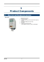
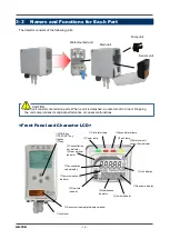
①
MODE key
Used to enter User and Maintenance Mode.
It is also used to cancel or skip in a specific mode.
②
TEST/SET key
Used to enter the test mode.
It is used for confirmation in a specific mode.
③
▲
key
Used to change screens or change a value (UP).
④
▼
key
Used to change screens or change a value (DOWN).
⑤
Lock lever
Lever to lock the main unit. Push it to attach or detach the main unit.
⑥
Sensor unit nameplate
display window
Window to view information on the currently installed sensor.
⑦
Power lamp (POWER)
Power lamp. Turns green when the power is on.
⑧
First alarm lamp
(ALM1)
First alarm lamp. Turns red when the first alarm is reached.
⑨
Second alarm lamp
(ALM2)
Second alarm lamp. Turns red when the second alarm is reached.
⑩
Fault lamp (FAULT)
Fault lamp. Turns yellow when an abnormality is detected in the detector.
⑪
Gas name display
Displays the gas name in chemical formula (e.g. Silane = SIH4).
⑫
Concentration value
display
Displays the gas concentration.
⑬
Unit display
Displays the unit according to the specification (ppm, ppb, vol%, %, %LEL).
⑭
Concentration bar
indicator
The detectable range (full scale = FS) is divided into 20 segments. The
increase in concentration is displayed in proportion to the full scale.
⑮
Alarm setpoint
indicator
The alarm setpoints (AL1 and AL2) are indicated on the concentration bar.
⑯
Flow rate indicator
Displays the flow rate. When the line is in the middle of the indicator, the
flow rate is normal (0.5 L/min).
⑰
Communication
indicator
For GD-70D-NT, this indicator is displayed while transmitting data with the
upper unit (TX, RX).
⑱
Maintenance indicator
Displayed while in Maintenance Mode. When this indicator is displayed, the
alarm contact is disconnected and there are no alarms.
⑲
Inhibit indicator
Displayed when the inhibition (point skip) is set.
⑳
Pyrolyzer unit
connection indicator
Displayed when the dedicated pyrolyzer unit (PLU-70) is connected.
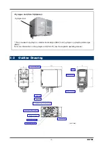
<Main Unit>
The main unit of the GD-70D houses the sensor unit, pump unit,
and circuitry for the detector. The main unit installs to the
mounting plate’s terminal plate.
<Pump Unit>
The pump unit gets installed in the main unit. It draws sample into the detector at 0.5 L/min.
Содержание GD-70D Series
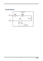
Страница 15: ... 15 GD 70D Tubing Diagram ...
Страница 43: ... 43 GD 70D Alarm Pattern L H Alarm Pattern L LL oxygen deficiency alarm ...
Страница 45: ... 45 GD 70D Alarm Pattern L H ...
Страница 58: ...GD 70D 58 Return to Detection Mode Press the TEST key for 3 seconds ...


