
20 June 2005
KEY COUNTER INSTALLATION
1-63
Installation
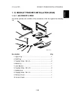
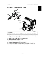
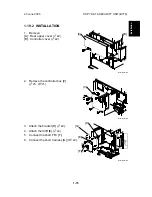
1.14 KEY COUNTER INSTALLATION
CAUTION
Unplug the machine power cord before starting the following procedure.
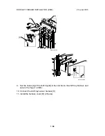
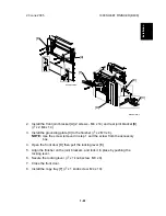
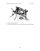
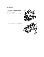
1. Hold the key counter plates [A] on the inside of the key counter bracket [B] and
insert the key counter holder [C]
2. Secure the key counter holder to the bracket (
x2).
3. Attach the key counter cover [D] (
x2).
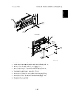
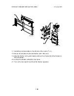
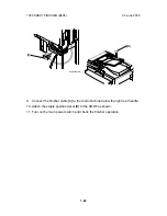
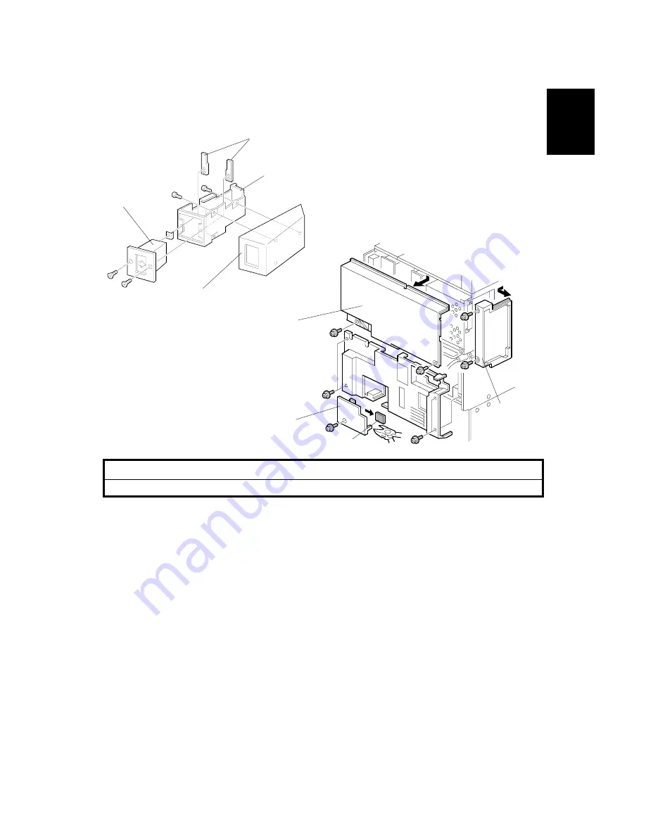
4. Remove the connector cover [E].
5. Remove the knockout [F] from the connector cover.
6. Remove the rear upper cover [G] (
x4) and left corner cover [H] (
x2).
A683I518.WMF
B543I001.WMF
[A]
[B]
[C]
[D]
[E]
[F]
[G]
[H]
Содержание A-C4
Страница 1: ...Model A C4 Machine Code B195 B198 B264 B265 SERVICE MANUAL 20 June 2005 Subject to change...
Страница 112: ...LEFT COVER 20 June 2005 3 8 3 8 LEFT COVER 1 Left upper cover A x4 2 Controller cover B x2 B195R955 WMF A B...
Страница 194: ...PRINTED CIRCUIT BOARDS 20 June 2005 3 90 3 19 5 PSU 1 Left cover 3 8 2 PSU A x4 x all B195R824 WMF A...