20 June 2005
1-BIN TRAY UNIT INSTALLATION (B544)
1-27
Installation
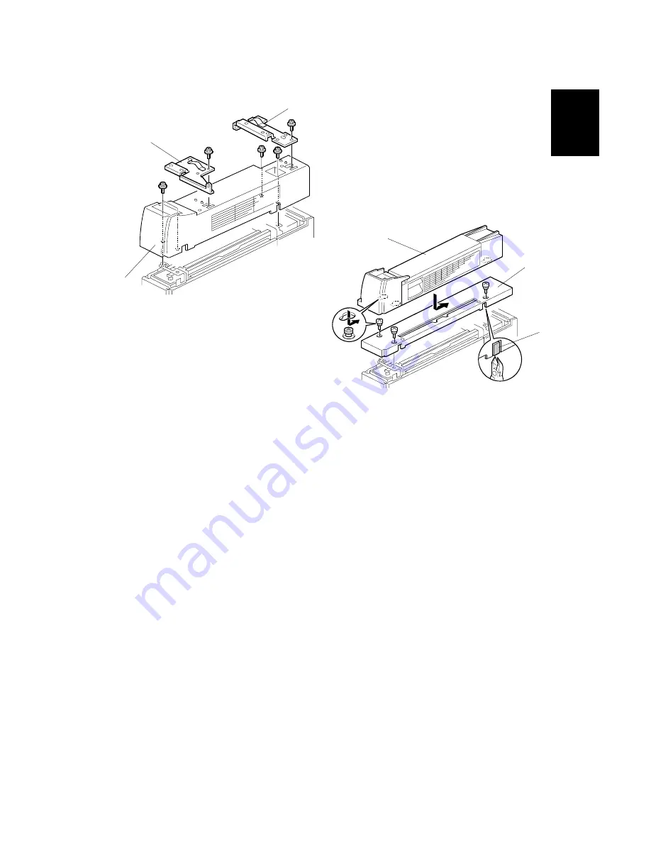
2. Unpack the 1-bin tray unit and remove the tapes.
3. Remove the front bracket [A] (
x 1) and rear bracket [B] (
x 1) from the top
of the paper exit cover [C].
4. Remove the paper exit cover [C] (
x 4).
5. Cut away two covers [D] from the base cover [E].
6. Trim the edges so they are smooth.
7. Install the base cover [E] (
x 3: stepped screw).
8. Set the 1-bin tray unit [F] on the base cover and slide onto the heads of the
stepped screws.
B544I201.WMF
B544I102.WMF
[A]
[B]
[C]
[D]
[E]
[F]
Содержание A-C4
Страница 1: ...Model A C4 Machine Code B195 B198 B264 B265 SERVICE MANUAL 20 June 2005 Subject to change...
Страница 112: ...LEFT COVER 20 June 2005 3 8 3 8 LEFT COVER 1 Left upper cover A x4 2 Controller cover B x2 B195R955 WMF A B...
Страница 194: ...PRINTED CIRCUIT BOARDS 20 June 2005 3 90 3 19 5 PSU 1 Left cover 3 8 2 PSU A x4 x all B195R824 WMF A...


