


INSTALLATION FLOW CHART
20 June 2005
1-6
1.2 INSTALLATION FLOW CHART
The following flow chart shows how to install the optional units more efficiently.
Bridge Unit:
Needed for the finishers and external output tray.
Paper Tray Unit:
Needed for LCT and finishers.
Other requirements:
See Overall Machine Information – Installation Option Table.
Unpack Copier
Install the copier
Install the bridge unit (if required)
Install the remaining options in any order
Place Copier on the paper tray unit
Install the paper tray unit
Does the user require the Paper Tray Unit, LCT, or Finisher?
Yes
No
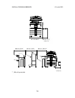
If the customer requires the 1-bin tray:
Remove the scanner unit
Install the 1-bin tray
Replace the scanner unit
B135I510.WMF
Содержание A-C4
Страница 1: ...Model A C4 Machine Code B195 B198 B264 B265 SERVICE MANUAL 20 June 2005 Subject to change...
Страница 112: ...LEFT COVER 20 June 2005 3 8 3 8 LEFT COVER 1 Left upper cover A x4 2 Controller cover B x2 B195R955 WMF A B...
Страница 194: ...PRINTED CIRCUIT BOARDS 20 June 2005 3 90 3 19 5 PSU 1 Left cover 3 8 2 PSU A x4 x all B195R824 WMF A...