


20 June 2005
SERVICE PROGRAM MODE TABLES
5-3
Service
Tables
5.2.3 SERVICE TABLES
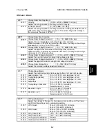
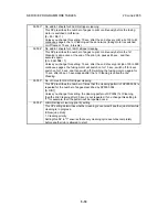
SP1-xxx: Feed
Leading Edge Registration
1001
*
Adjusts the printing leading edge registration using the trimming area pattern
(SP2-902-3, No.11).
[+9 ~ –9 /
3.0
/ 0.1 mm]
Use
to toggle between
±
before entering the value. Specification: 3
±
2 mm
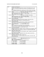
Side-to-Side Registration
1002
*
Adjusts the printing side-to-side registration from the 3rd paper feed station using
the trimming area pattern (SP2-902-3, No.11).
Tray3, Tray4 for Paper Feed Unit.
Use the
key to toggle b and – before entering the value. Specification:
2
±
1.5 mm
1002 1 Tray 1
[–9 ~ +9/
+3.0 mm
/ 0.1 mm step]
1002 2 Tray 2
[–9 ~ +9/
+3.0 mm
/ 0.1 mm step]
1002 3 Tray 3
[–9~ +9/
+2.0 mm
/ 0.1 mm/step]
1002 4 Tray 4
[–9~ +9/
+2.0 mm
/ 0.1 mm/step]
1002 5 From Duplex Unit
[–9 ~ +9/
+0.0 mm
/ 0.1 mm/step]
1002 6 Bypass Feed
[–9 ~ +9/
+3.0 mm
/ 0.1 mm/step]
1002 7 LCT (if present)
[–9 ~ +9/
+1.5 mm
/ 0.1 mm/step]
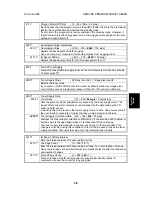
Registration Buckle Adjustment
1003
*
Adjusts the relay clutch timing at registration. Relay clutch timing determines the
amount of paper buckle at registration. (A “+” setting causes more buckling.)
1003 1 Trays 2,3,4 LCT
1003 2 Duplex
1003 3 Bypass
[–9 ~+9 /
0 /
1 mm step]
1003 4 Tray 1 Feed
[–9 ~+9 /
1 /
1 mm step]
1003 5 Bypass Thick Paper
[–9 ~+9 /
-2 /
1 mm step]
By-pass Feed Paper Size Display
1007
*
Displays the paper width sensor data for the by-pass feed table.
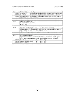
Exit Junction Solenoid Start Timing
1012
*
Adjusts the timing of the solenoids at the entrance and exit of the paper exit
section to accommodate the increased speed of the duplex unit.
This SP has been added to compensate for the increased operation speed of the
duplex unit for this machine. Increase the value if the leading edges are jamming.
Decrease the value if trailing edges are bending at the entrance
1012 1* Exit Entrance Junction
Solenoid
35 CPM: [200 ~ 450 ms /
370 ms
/ 10 ms]
45 CPM: [200 ~ 450 ms /
300 ms
/10 ms]
1012 2* Exit Last Junction Solenoid
35 CPM: [200 ~ 450 ms /
370 ms
/ 10 ms]
45 CPM: [200 ~ 450 ms /
370 ms
/10 ms]]
Содержание A-C4
Страница 1: ...Model A C4 Machine Code B195 B198 B264 B265 SERVICE MANUAL 20 June 2005 Subject to change...
Страница 112: ...LEFT COVER 20 June 2005 3 8 3 8 LEFT COVER 1 Left upper cover A x4 2 Controller cover B x2 B195R955 WMF A B...
Страница 194: ...PRINTED CIRCUIT BOARDS 20 June 2005 3 90 3 19 5 PSU 1 Left cover 3 8 2 PSU A x4 x all B195R824 WMF A...