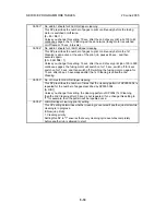
20 June 2005
SERVICE PROGRAM MODE TABLES
5-19
Service
Tables
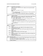
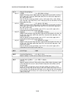
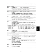
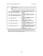
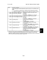
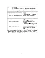
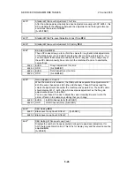
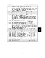
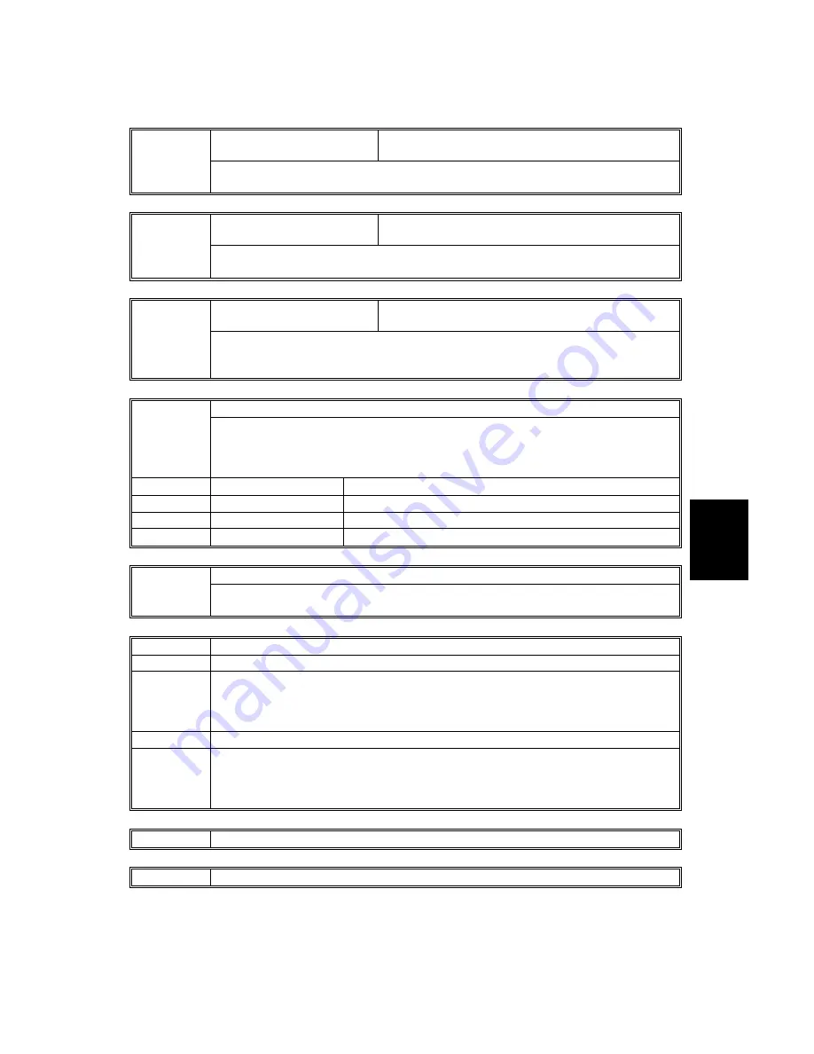
SP4-xxx: Scanner
Scanner Sub Scan
Magnification
[–0.9 ~ 0.9 /
0.0
/ 0.1% step]
4008*
Adjusts the magnification of the sub scan direction during scanning. Changing this
value changes the scanner motor speed. Press
to toggle
±
.
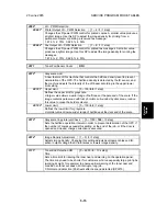
Scanner Leading Edge
Registration
[–0.9 ~ 0.9 /
0.0
/ 0.1 mm step]
4010*
Adjusts the leading edge registration for scanning. Press
to toggle
±
.
As you enter a negative value, the image moves toward the leading edge.
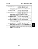
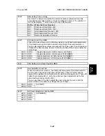
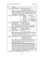
Scanner Side-to-Side
Registration
[–4.6 ~ +4.6 /
0.0
/ 0.1 mm step]
4011*
Adjusts side-to-side registration for scanning. Press
to toggle
±
.
As you enter negative values, the image will disappear at the left, and as you
enter positive values, the image will appear at the left.
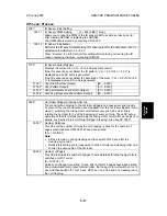
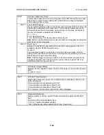
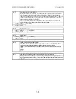
Scanner Erase Margin
4012*
Adjusts scanning margins for the leading and trailing edges (sub scan) and right
and left edge (main scan).
Do not adjust unless the customer desires a scanner margin greater than the
printer margin.
4012 1* Leading Edge
[0 ~ 9 /
1.0
/ 0.1 mm step] (Specification: 3
±
2 mm)
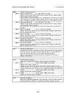
4012 2* Trailing Edge
[0 ~ 9 /
0.5
/ 0.1 mm step] (Specification: 2
±
2 mm)
4012 3* Right
[0 ~ 9 /
0.5
/ 0.1 mm step] (Specification: +2.5 ~ -1.5 mm)
4012 4* Left
[0 ~ 9 /
1.0
/ 0.1 mm step] (Specification: 2
±
1.5 mm)
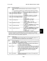
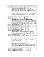
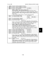
Scanner Free Run
4013
Performs a scanner free run with the exposure lamp off.
[OFF] [ON]
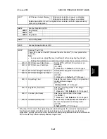
4016
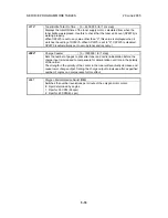
White Board Read Adjust
4016 1 Read Start Position
Adjusts the scanning start position on the white plate for auto shading. The default
is 10.5 mm from the leading edge. The setting specifies how far scanning starts
from the default position.
[–5.0 ~ +5.0 /
0.0
/ 0.1 mm/step]
4016 2 Read Width
Adjusts the width of the area on the white plate (in the sub scan direction) that is
scanned for auto shading. The default is 4.76 mm. The current setting specifies
the difference from this default.
[–5.0 ~ +5.0 /
0.0
/ 0.1 mm/step]
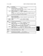
4018
Scanner Optical Adjust Axis
DFU
4019
Scanner Read Position
DFU
Содержание A-C4
Страница 1: ...Model A C4 Machine Code B195 B198 B264 B265 SERVICE MANUAL 20 June 2005 Subject to change...
Страница 112: ...LEFT COVER 20 June 2005 3 8 3 8 LEFT COVER 1 Left upper cover A x4 2 Controller cover B x2 B195R955 WMF A B...
Страница 194: ...PRINTED CIRCUIT BOARDS 20 June 2005 3 90 3 19 5 PSU 1 Left cover 3 8 2 PSU A x4 x all B195R824 WMF A...


